High-lift distributed active flow control system and method

Inactive Publication Date: 2006-05-18
THE BOEING CO
View PDF89 Cites 50 Cited by
  • Summary
  • Abstract
  • Description
  • Claims
  • Application Information

AI Technical Summary

Benefits of technology

[0013] Various embodiments of the present invention desirably increase lift by engaging boundary layer control units (i.e., active flow control units) to delay the onset of boundary layer separation when the wing, flaps, slats, and other flight control surfaces are deflected at angles beyond which they are conventionally unable to maintain attached (non-separated) airflow (e.g., a highly cambered airfoil configuration

Problems solved by technology

The primary challenge for STOL aircraft involves designing the aircraft to effectively achieve a shortened take-off distance.
Increasing thrust requires use of larger, more-powerful engines that add weight to the aircraft and consume greater quantities of fuel.
Unfortunately, however, added wing size means added drag and weight during stable flight resulting in greater fuel consumption and slower cruising speeds.
Despite the lift improvements referenced above, coupled aero-propulsion systems include a number of drawbacks that significantly detract from their desirability.
For example, maintenance issues plague many designs as they require internal ducting of hot exhaust gases and/or deflecting hot gases over the wing and flap surfaces.
Coupled aero-propulsio

Method used


Image

  • High-lift distributed active flow control system and method
  • High-lift distributed active flow control system and method
  • High-lift distributed active flow control system and method

Examples


Embodiment Construction

[0021] The present inventions now will be described more fully hereinafter with reference to the accompanying drawings, in which some, but not all embodiments of the inventions are shown. Indeed, these inventions may be embodied in many different forms and should not be construed as limited to the embodiments set forth herein; rather, these embodiments are provided so that this disclosure will satisfy applicable legal requirements. Like numbers refer to like elements throughout.

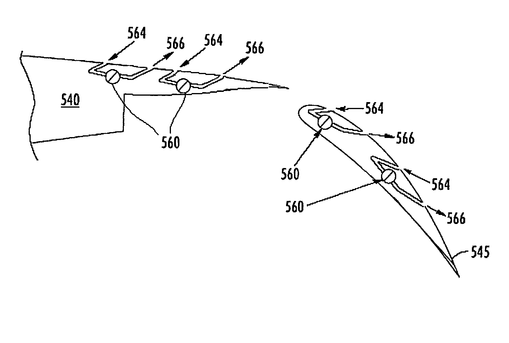
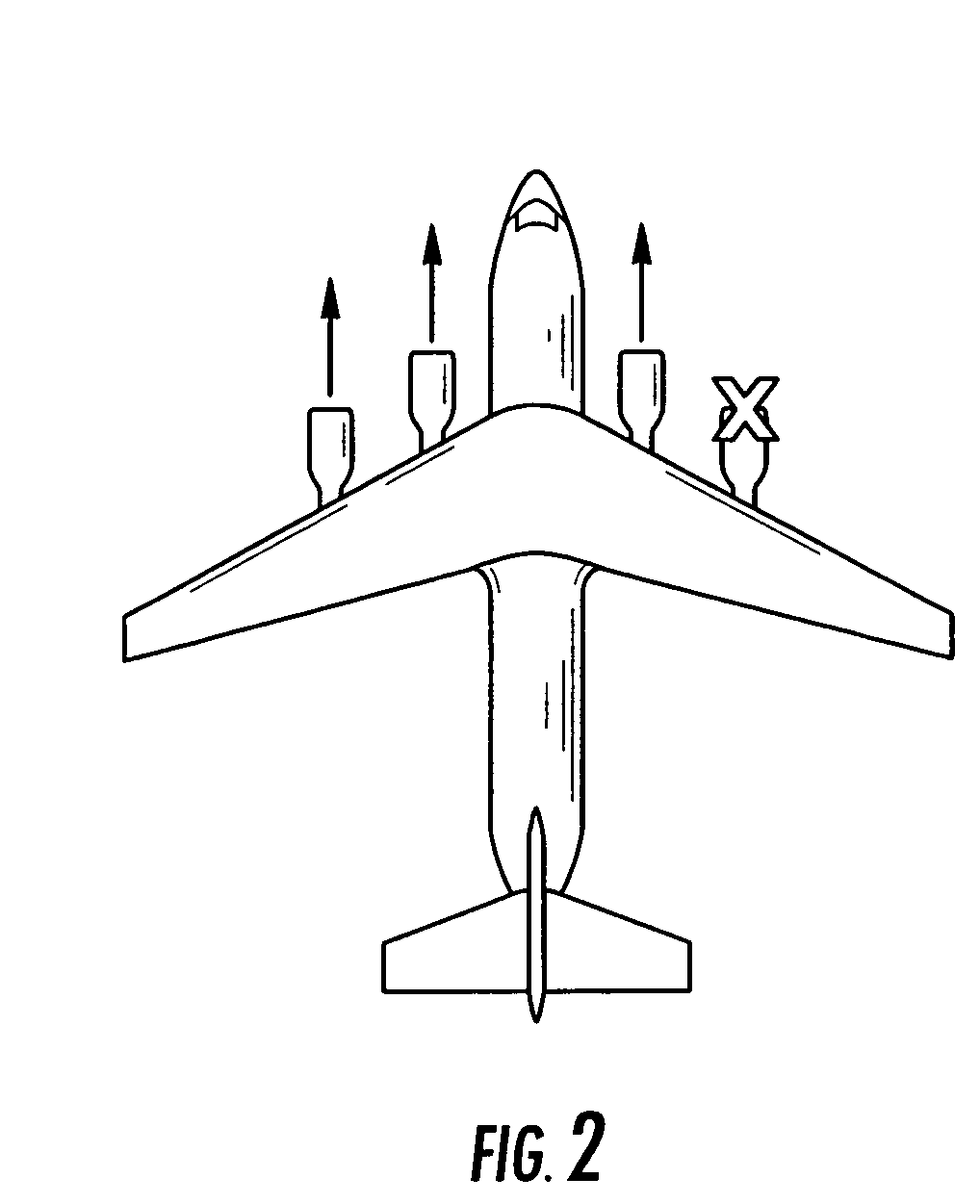
[0022] Various embodiments of the present invention are directed to powered distributed active flow control (“DAFC”) systems. As discussed in detail below, DAFC systems according to various embodiments of the invention include non-coupled, aero / propulsion high-lift systems that minimize the adverse effects of engine-out by reducing asymmetric moments. Although the forgoing discussion focuses primarily on DAFC systems configured for aircraft, it is noted that the DAFC systems described herein may be similarly...


PUM


Abstract

The present invention is directed to a distributed active flow control (“DAFC”) system that maintains attached airflow over a highly cambered airfoil employed by an aircraft or other similar applications. The DAFC system includes a primary power source comprised of one or more aircraft engines, one or more power conversion units, and optionally, one or more auxiliary power units. The power conversion units are coupled to one or more aircraft engines for supplying power to a distribution network. The distribution network disperses power from the one or more power conversion units to active flow control units disposed within one or more aircraft flight control surfaces (e.g., the aircraft wing, the tail, the flaps, the slats, the ailerons, and the like). In one embodiment, an auxiliary power unit is included for providing a redundant and auxiliary power supply to the distribution network. In another embodiment, a back-up power source is provided in communication with the distribution network for providing an additional redundant power supply.

Description

BACKGROUND OF THE INVENTION [0001] 1. Field of the Invention [0002] This invention relates generally to aircraft lift control systems, more particularly to a powered, lift-enhancing distributed active flow control system that operates safely despite the loss of a single aircraft engine. [0003] 2. Description of the Related Art [0004] It has long been desirable to produce aircraft, especially jet aircraft, which are capable of taking-off and / or landing despite relatively short runway distances. Such aircraft are conventionally referred to as Short Take-Off and Landing (“STOL”) aircraft and include, for example, the Boeing YC-14, the McDonnell Douglas YC-15, and the USAF C-17 transport aircraft. [0005] The primary challenge for STOL aircraft involves designing the aircraft to effectively achieve a shortened take-off distance. Typically, this is accomplished through increasing the aircraft's thrust, through increasing the aircraft's lift, or through some combination of both. Increasing...

Claims


Application Information

Patent Timeline
IPC IPC(8): B64C21/06
CPCB64C21/04B64C21/08Y02T50/166B64C2230/04Y02T50/10
Inventor MANLEY, DAVID J.
Owner THE BOEING CO
Why Eureka
Try Eureka