Rotating electric machine

a technology of rotating electric machines and electric motors, which is applied in the direction of magnetic circuit rotating parts, battery/fuel cell control arrangement, shape/form/construction, etc., can solve the problems of lowering the driving efficiency of electric motors, and achieve the effect of improving the efficiency of dynamo-electric machines, reducing iron loss due to eddy current, and easy alignmen

Inactive Publication Date: 2006-05-18
YAMAHA MOTOR CO LTD
View PDF6 Cites 35 Cited by
  • Summary
  • Abstract
  • Description
  • Claims
  • Application Information

AI Technical Summary

Benefits of technology

[0024] As a consequence, in comparison with the case in which the leaked magnetic flux is proceeded directly to the yoke, generation of an eddy current caused by the leaked magnetic flux may be restrained by insulation resistances at the portions of the teeth being inserted into the yoke.
[0025] Therefore, iron loss due to an eddy current may be reduced, and thus the efficiency of the dynamo-electric machine may be improved.
[0026] According to the dynamo-electric machine according to the second embodiment, since the cross-sectional area of the magnet-opposed end portions of the teeth oppo

Problems solved by technology

The induced current causes Joule heat, and the Joule heat increases loss (loss

Method used


Image

  • Rotating electric machine
  • Rotating electric machine
  • Rotating electric machine

Examples


first embodiment

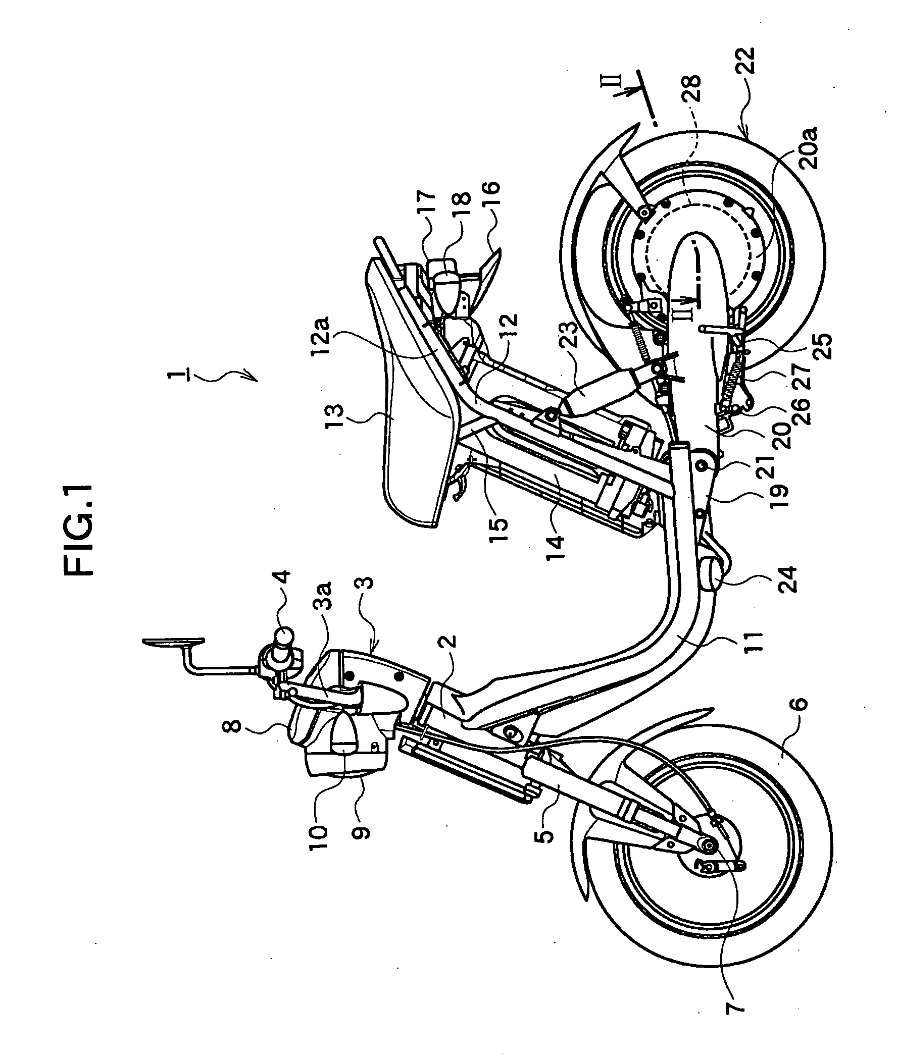
[0047]FIG. 1 is a side view of an electric motorcycle 1 as an example of an apparatus on which an axial gap dynamo-electric machine according to a first embodiment of the present invention is mounted.

[0048] As shown in FIG. 1, the electric motorcycle 1 includes a head pipe 2 at the upper front of a vehicle body, and the head pipe rotatably accommodates a steering shaft, not shown, for changing the direction of the vehicle body therein. A handle supporting member 3 on which a handle 3a is fixed is mounted at the upper end of the steering shaft, and grips 4 are mounted to both ends of the handle 3a. The right (far side of FIG. 1) grip 4, not shown, constitutes a rotatable throttle grip.

[0049] A pair of left and right front forks 5 are mounted to the head pipe 2 downward from the lower end thereof. At the respective lower ends of the front forks 5, a front wheel 6 is mounted via a front axle 7, and the front wheel 6 is rotatably supported by the front axle 7 in a state of being suspe...

second embodiment

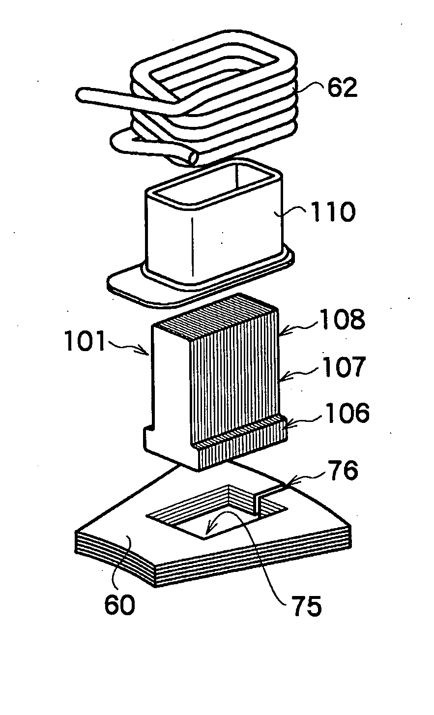
[0100]FIG. 8A is a perspective view showing a general construction of a tooth 91 and a portion of a stator yoke 92 where the tooth is mounted according to the present embodiment, and FIG. 8B is a drawing of the tooth 91 in FIG. 8A when viewed in the direction of lamination.

[0101] Since the components other than the tooth 91 and the stator yoke 92 are substantially the same as the first embodiment, the description will be omitted or made only briefly.

[0102] As shown in FIG. 8A, a stator rotor 92 is formed with square insertion holes 93 for inserting (fitting) and fixing the respective teeth 91 substantially in the shape of a partly removed circle (substantially C-shape) at predetermined circumferential pitches, and a pair of longitudinal inner surfaces 93a, 93b of each of the insertion holes 93 face the center axis BO.

[0103] In addition, on the inner surface 93b on the side of the outer peripheral surface 91a of the stator yoke 92 out of the longitudinal inner surfaces 93a, 93b of...

third embodiment

[0118]FIG. 9A is a perspective view showing a general construction of a tooth and the portion of a stator yoke where the tooth is mounted according to a third embodiment of the present invention, and FIG. 9B is a drawing of the tooth in FIG. 9A when viewed in the direction of lamination.

[0119] Since the components other than teeth 101 are substantially the same as in the first embodiment, description will be omitted or made only briefly.

[0120] In the present embodiment, as shown in FIG. 9A and FIG. 9B, each of the teeth 101 is constructed by laminating a plurality of steel plates 102 of substantially T-shape.

[0121] Each of the steel plate 102 includes one end portion 102a having a predetermined width W7 along the shorter side of the steel plate 102 and a predetermined length along the longitudinal side of the steel plate 102, a midsection 102b extending from the one end portion 102a along the longitudinal direction by a predetermined length and having a width W7 which is the same...


PUM


Abstract

The present invention restrains generation of an eddy current caused by leaked magnetic flux, and reduces iron loss due to the eddy current.
A tooth 61 is mounted to a stator yoke 60 in a state in which at least part of it (a portion 81 to be inserted into the yoke) is inserted into an insertion hole 75 formed through the magnet-opposed surface of the stator yoke 60, and the cross-sectional area S1 (See FIG. 6A) of the portion 81 of the tooth 61 to be inserted into the yoke, which is taken perpendicularly with respect to lines of magnetic force B1 generated at the tooth 61 when a coil 62 is energized, is larger than the cross-sectional area S2 (See FIG. 6B) of the portion 82 to be disposed within the coil of the tooth 61, which is taken perpendicularly with respect to the lines of the magnetic force B1.

Description

TECHNICAL FIELD [0001] The present invention relates to a dynamo-electric machine of axial gap or radial gap type. BACKGROUND ART [0002] A radial gap electric motor as a radial gap dynamo-electric machine used for a drive source in an electric motorcycle or for other general electric motors has such a construction that a yoke of a rotor (rotor yoke) and a yoke of a stator (stator yoke) having a revolving shaft supported by bearings are opposed to each other, and the opposed surfaces are parallel with the revolving shaft. The opposed surface of the rotor yoke is provided with a magnet for a magnetic field in a cylindrical shape, and the opposed surface on the side of the stator is provided with a plurality of teeth arranged in a radial shape so as to oppose the cylindrical surface, and each tooth being wound by a coil. In other words, in the radial gap electric motor, the opposing surfaces of the magnet and the teeth are parallel with the revolving shaft, and the gap between the oppo...

Claims


Application Information

Patent Timeline
IPC IPC(8): H02K21/12H02K1/28H02K1/22H02K1/14H02K3/18H02K3/52H02K7/14H02K21/24
CPCH02K1/148Y02T90/127H02K7/14H02K21/24H02K2203/06H02K7/006B60L11/1803B60L11/1822B60L11/1864B60L11/1877B60L2200/12B60L2210/40B60L2220/14B60L2220/50Y02T10/7005Y02T10/7241Y02T10/7061Y02T10/7072Y02T90/124Y02T10/641Y02T90/14H02K3/522B60L50/51B60L53/80B60L58/21B60L50/66Y02T10/64Y02T10/70Y02T10/72Y02T90/12
Inventor NAITO, SHINYAHINO, HARUYOSHIISHIHARA, HIROYUKIMUROTA, KEIKOTERADA, JUNJI
Owner YAMAHA MOTOR CO LTD
Why Eureka
Try Eureka