Ultra wideband internal antenna

a wideband, internal antenna technology, applied in the direction of resonant antennas, elongated active element feeds, radiating element structural forms, etc., can solve the problems of difficult to design the external shape of helical antennas to provide attractive and portable terminals, body, and sar characteristics of absorption rate (sar), and achieve the effect of easy miniaturization

Inactive Publication Date: 2006-05-18
SAMSUNG ELECTRO MECHANICS CO LTD
View PDF4 Cites 76 Cited by
  • Summary
  • Abstract
  • Description
  • Claims
  • Application Information

AI Technical Summary

Benefits of technology

[0015] Accordingly, the present invention has been made keeping in mind the above problems occurring in the prior art, and an object of the present in

Problems solved by technology

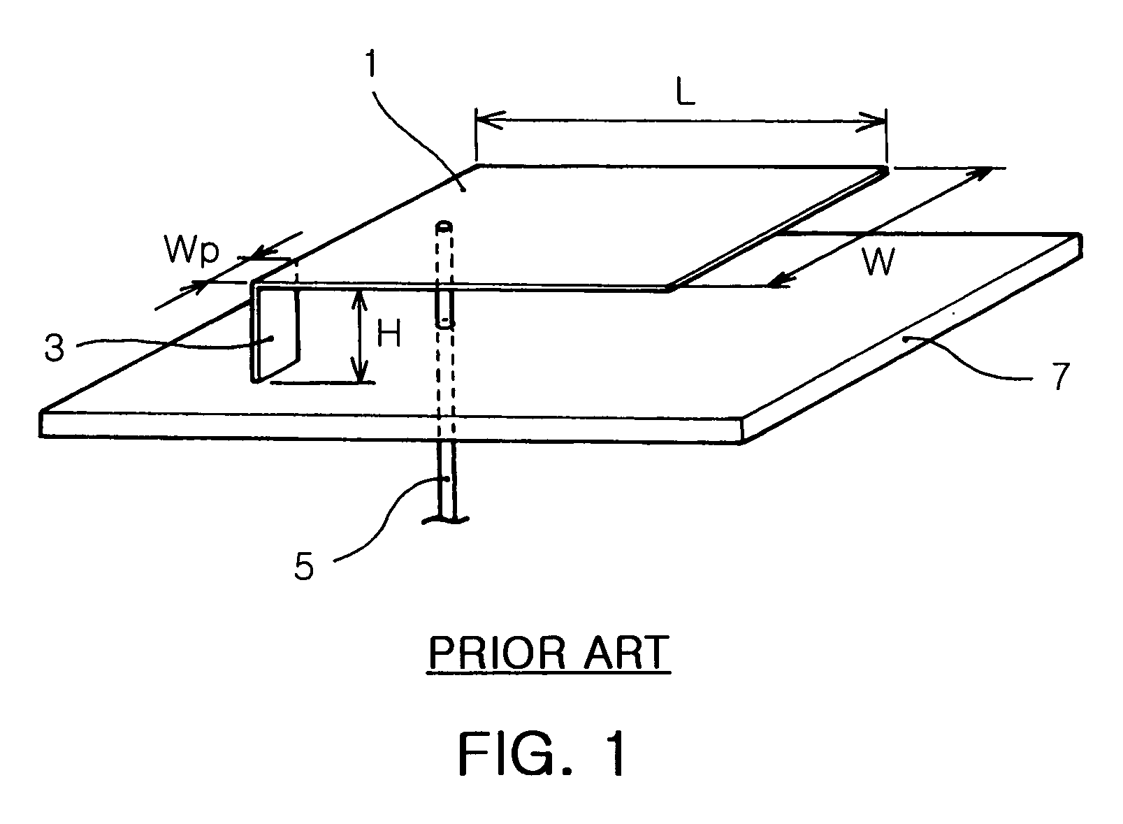
Such an antenna is advantageous in that it can obtain a high gain, but disadvantageous in that Specific Absorption Rate (SAR) characteristics, which are the measures of an electromagnetic wave's harm to the human body, are worsened due to the omni-directionality thereof.
Further, since the helical antenna is designed to protrude outward from a terminal, it is difficult to design the external shape of the helical antenna to provide an attractive and portable terminal.
Since the monopole antenna requires a separate space sufficient for the length thereof in a terminal, there is a disadvantage in that product design toward the miniaturization of terminals is hindered.
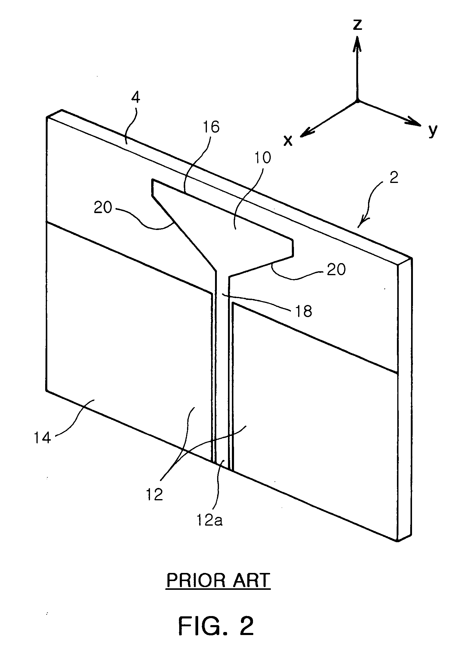
In such a wideband technology, the development of low power consumption and low cost semiconductor devices, the standardization of Media Access Control (MAC) specifications, the development of actual application layers, and the establishment of evaluation methods in high frequency wideband wireless communication have become major iss

Method used


Image

  • Ultra wideband internal antenna
  • Ultra wideband internal antenna
  • Ultra wideband internal antenna

Examples


first embodiment

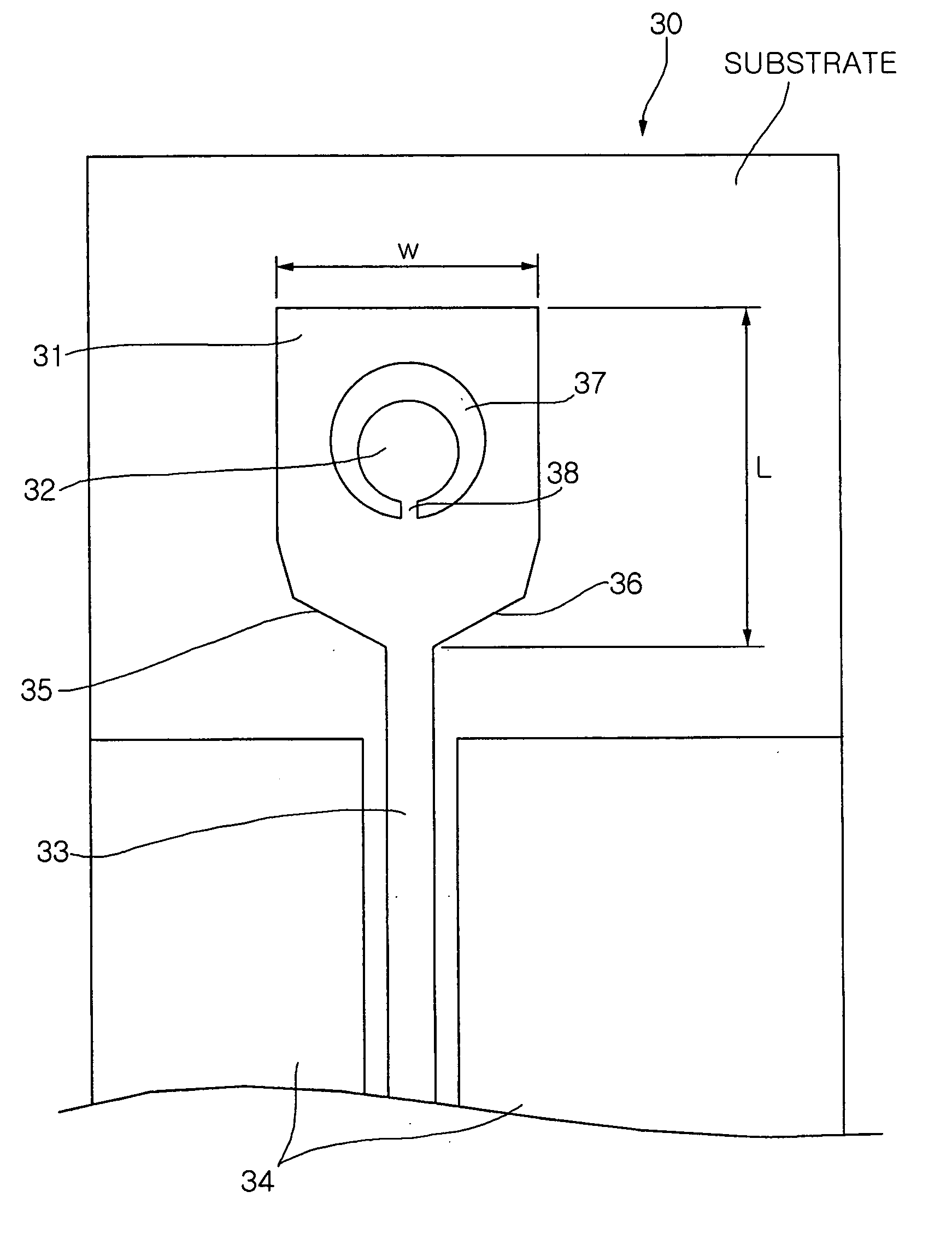
[0032]FIG. 3 is a view showing the construction of an ultra wideband internal antenna according to the present invention.

[0033] Referring to FIG. 3, an ultra wideband internal antenna 30 according to a first embodiment of the present invention is formed on a top surface of a dielectric substrate, and includes a first radiation part 31, a second radiation part 32, a feeding part 33 and ground parts 34.

[0034] The first radiation part 31 may be made of a thin metal plate having an outer circumference formed in a substantially rectangular shape, and preferably formed in a rectangle shape having a vertical length (L) slightly greater than a horizontal width (W). For example, the first radiation part 31 can be miniaturized to such an extent that its length (L)×its width (W) is approximately 1 cm×0.7 cm. Further, the first radiation part 31 has cut parts 35 and36 formed by cutting out lower corner portions of the first radiation part 31. As shown in FIG. 3, each of the cut parts 35 and 36...

second embodiment

[0043]FIG. 5 is a view showing the construction of an ultra wideband internal antenna according to the present invention.

[0044] Referring to FIG. 5, an ultra wideband internal antenna 50 according to the second embodiment of the present invention is formed on a top surface of a dielectric substrate, and includes a first radiation part 31, a second radiation part 32, a feeding part 33 and a ground part 34, and additionally includes stubs 51 and 52 connected to the first radiation part 31.

[0045] The stubs 51 and 52 are formed in the shape of long striplines, and connected to cut parts 35 and 36 formed on the first radiation part 31 while protruding from the cut parts 35 and 36. Preferably, the stubs 51 and 52 are symmetrically formed around the feeding part 33. Further, the number of stubs 51 and 52 may be one, two or more depending on the frequency bands to be cut off by the antenna 50 according to the second embodiment of the present invention. Further, the stubs 51 and 52 can be f...


PUM


Abstract

The present invention relates to an ultra wideband internal antenna, which is provided in a mobile communication terminal to cut off frequencies in a certain frequency band while processing ultra wideband signals. The ultra wideband internal antenna includes a first radiation part, a second radiation part, a feeding part and a ground part. The first radiation part is made of a metal plate on a top surface of a dielectric substrate and is provided with at least one cut part, formed by cutting out a lower corner portion thereof, and an internal slot. The second radiation part is formed in the slot of the first radiation part while being connected to the first radiation part, the second radiation part being conductive. In this case, the first and second radiation parts form an ultra wide band due to electromagnetic coupling therebetween using individual currents flowing into the first and second radiation parts.

Description

RELATED APPLICATIONS [0001] The present application is based on, and claims priority from, Korean Application Number 2004-0093011, filed Nov. 15, 2004, the disclosure of which is incorporated by reference herein in its entirety. BACKGROUND OF THE INVENTION [0002] 1. Field of the Invention [0003] The present invention relates generally to an antenna provided in a mobile communication terminal to transmit and receive radio signals and, more particularly, to an ultra wideband internal antenna, which is provided within a mobile communication terminal and is capable of cutting off frequencies in a specific frequency band while processing ultra wideband signals. [0004] 2. Description of the Related Art [0005] Currently, mobile communication terminals are required to provide various services as well as be miniaturized and lightweight. To meet such requirements, internal circuits and components used in the mobile communication terminals trend not only toward multi-functionality but also tow...

Claims


Application Information

Patent Timeline
IPC IPC(8): H01Q1/38
CPCH01Q5/364H01Q9/40H01Q13/08
Inventor LEE, JAE CHAN
Owner SAMSUNG ELECTRO MECHANICS CO LTD
Why Eureka
Try Eureka