Fiber optic panel illuminated mailbox

Inactive Publication Date: 2006-05-18
BOSSOMO ROBERT J
View PDF16 Cites 8 Cited by
  • Summary
  • Abstract
  • Description
  • Claims
  • Application Information

AI Technical Summary

Benefits of technology

[0011] The unique combination of the aforesaid has yet to be assembled and utilized in a mailbox address number illumination application. Utilization of high output illumination LEDs along with a fiber optic light emitting panel allows for the unique function of the present art. Fiber optic panels have traditionally been utilized for back lighting liquid crystal displays. U.S. Pat. No. 4,885,663 issued to Parker on Dec. 5, 1989 describes the technology of fiber optic panel construction. Said panels are typically woven from plastic optical fibers in a unique bending form which provides a panel which has a uniform illumination across its surface. The unique uniform light distribution across said panel, allows said panel to be fed from a low power consumption point source such as an LED and yet uniformly illuminate a cutout of address numbers within a mailbox post. As aforesaid, the combination of a high output LED which utilizes low power and the aforesaid fiber optic panel allows the modest energy available from the solar charged battery system to fully illuminate the address numbers during the nighttime hours.

Problems solved by technology

Without illumination, the address number is difficult to see and locate at night.
The prior art necessity of running electrical power wiring from the main utility power supply created a labor intensive mailbox installation process.
That is, installing a mailbox is a relatively quick and easy task but running, burying, and connecting electric wire cables is quite time consuming and often requires specialized and skilled labor.
As can be seen from the prior art, the traditional tradeoff of nightime illumination energy required and daytime solar energy collected has precluded the prior art from utilizing solar energy and forced said inventors to utilize main utility power with the inherent complexities of installation.
Utilization of a single LED alone without said illumination panel would not fully illuminate the address number cutouts in said post since the light cannot be uniformly distributed across the address number area.

Method used


Image

  • Fiber optic panel illuminated mailbox
  • Fiber optic panel illuminated mailbox
  • Fiber optic panel illuminated mailbox

Examples


Embodiment Construction

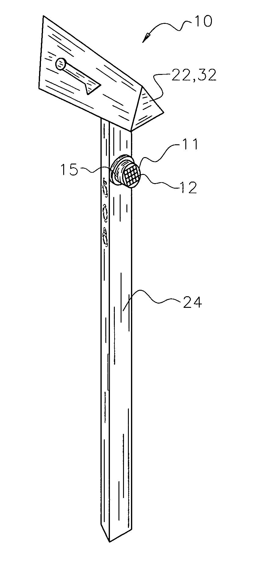
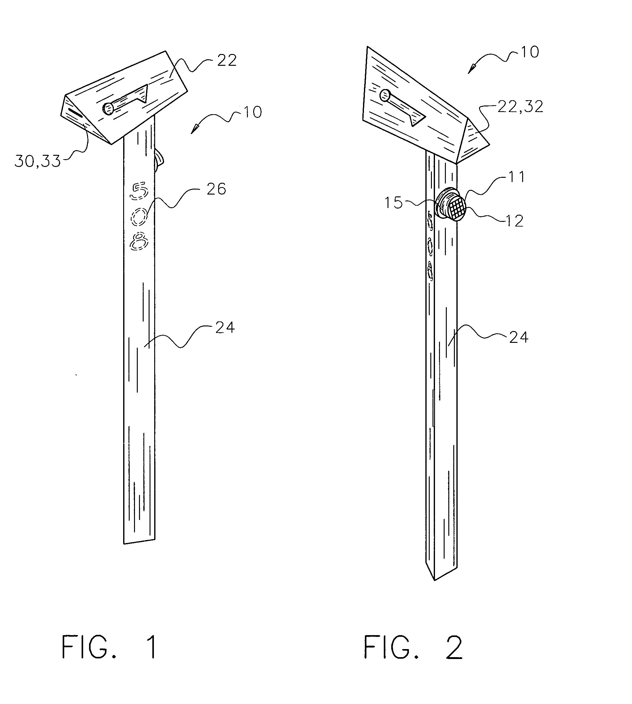
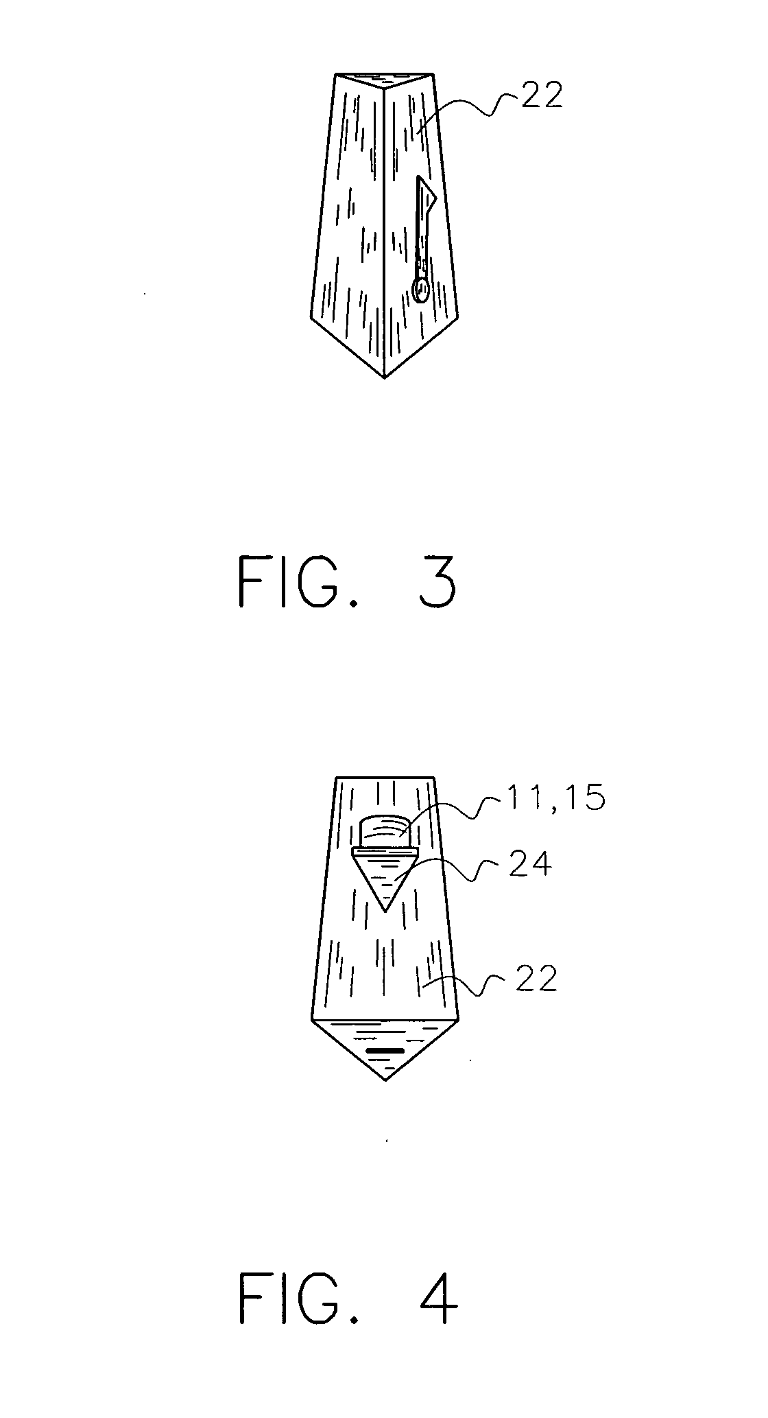
[0030] Referring now to the drawings, there is shown a preferred embodiment of the fiber optic panel illuminated mailbox. As aforesaid, the fiber optic panel illuminated mailbox 10 comprises a solar cell 12 energy collector of minimal size, control circuitry 14, battery 16 storage, a light emitting diode (LED) 18 illumination source feeding a fiber optic panel 20, a mail box 22, and a mounting post 24 having address number or other shaped cutouts 26 behind which is mounted said fiber optic panel 20.

[0031] In a preferred embodiment, the mailbox 22 comprises a substantially triangular external cross section which tapers from a front portion 30 to a rear portion 32. The mailbox 22 preferably has a hinged and substantially triangular door 33 at said front portion 30. The mounting post 24, also in a preferred embodiment, comprises a substantially uniform hollow triangular tubular cross section with one or more identifying cutouts 26 which represent address numbers of the location. Alter...


PUM


Abstract

A fiber optic panel illuminated mailbox having a solar energy collection system and a control circuit which illuminates a light emitting diode which feeds a fiber optic panel. The fiber optic panel is placed behind cutouts which represent address numbers in order to provide mailbox address location during nighttime hours. The control circuitry turns on the light emitting diode during nighttime hours and charges batteries during daytime hours. The fiber optic panel illuminated mailbox is a self contained illuminated mailbox address number identification system which does not require external wiring.

Description

BACKGROUND OF THE INVENTION [0001] The present invention relates in general to illuminated mailboxes, and more particularly, to an illuminated mailbox which utilizes solar power and one or more fiber optic illumination panels fed with one or more low power consumption and high lumen output light emitting diodes (LEDs). The present invention represents a unique illuminated mailbox apparatus which collects and stores solar power during daylight hours, automatically turns on an LED during nighttime hours, and feeds the LED light through a fiber optic bundle to a fiber optic illumination panel located behind the street number openings or cutouts on the post of the mailbox. [0002] Mailboxes are often placed near the road or street on which a residence or business is located and serve to display the address number at the location in addition to the traditional mail collection function. Traditionally, the address number is marked or painted upon the mailbox or mailbox post. Without illumin...

Claims


Application Information

Patent Timeline
IPC IPC(8): F21S8/00
CPCA47G29/1209F21V33/006G02B6/001
Inventor BOSSOMO, ROBERT J.
Owner BOSSOMO ROBERT J
Why Eureka
Try Eureka