Optical device and light control method
a technology of optical devices and light control methods, applied in the field of optical communication, can solve the problems of flatness of transmission loss characteristics and substantially reduced wavelength channel spectral, and achieve the effect of improving the uniformity of transmission loss with respect to the wavelength of spectrum
- Summary
- Abstract
- Description
- Claims
- Application Information
AI Technical Summary
Benefits of technology
Problems solved by technology
Method used
Image

Examples
first embodiment
[A] Description of First Embodiment
[0079] [A-1] Configuration
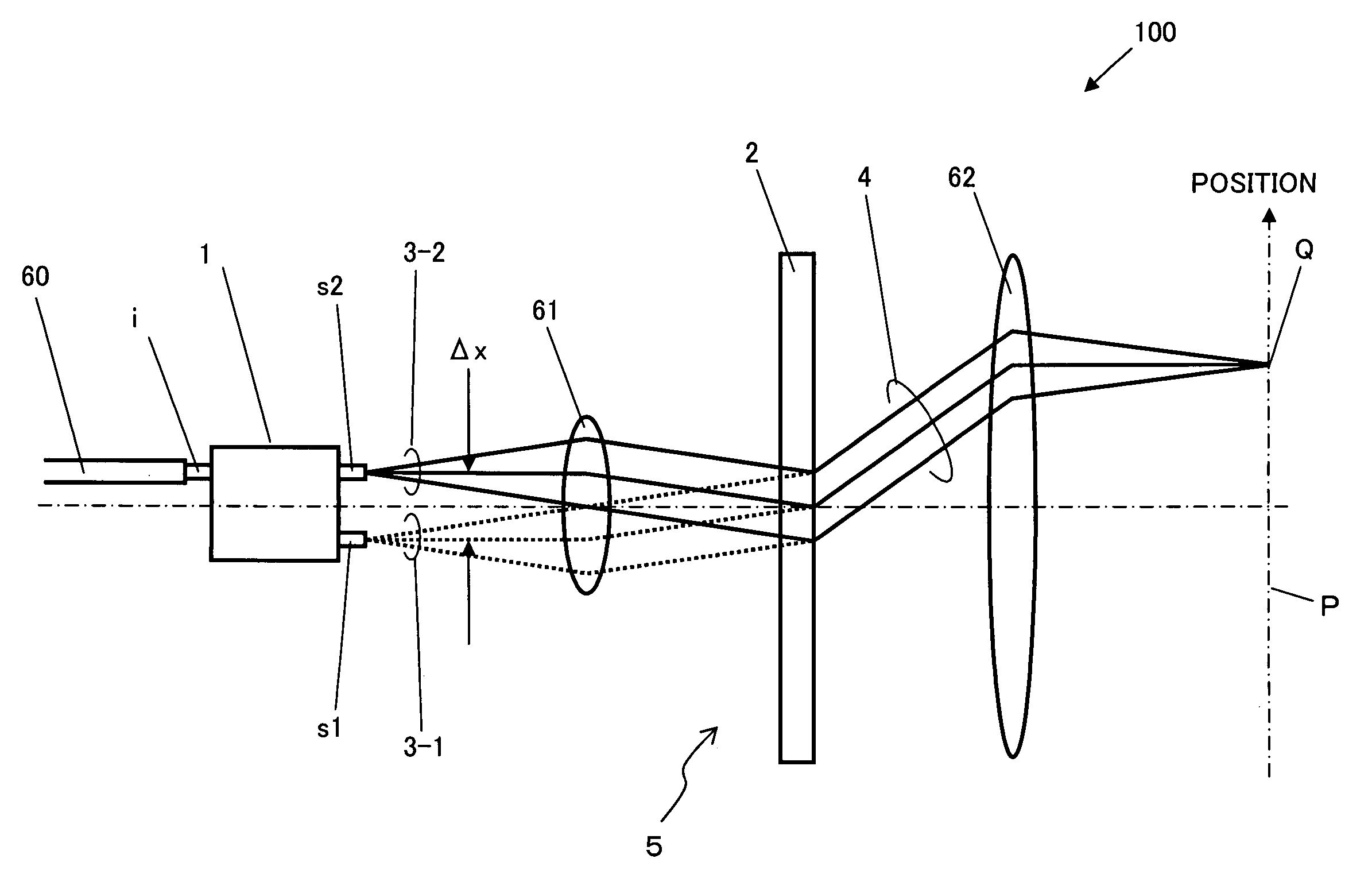
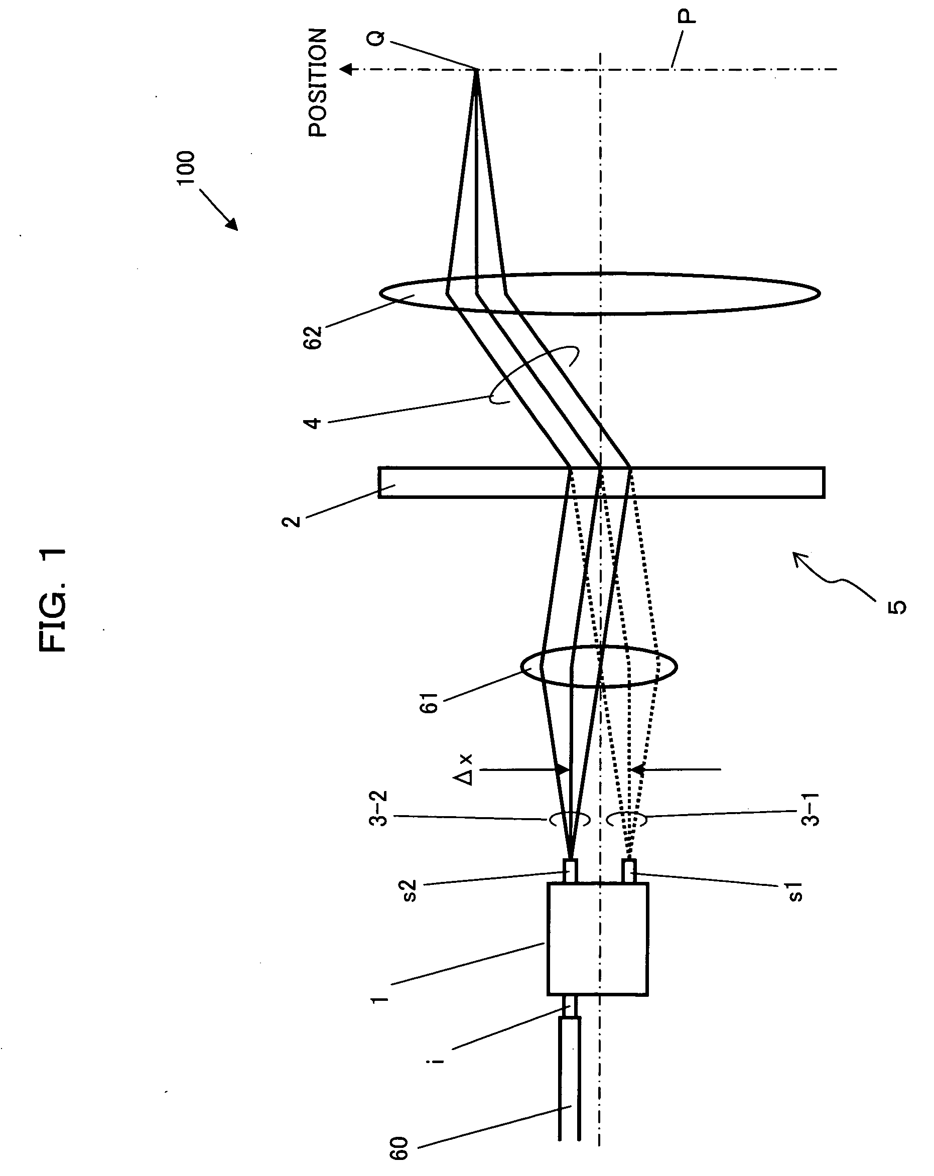
[0080]FIG. 1 is a diagram showing an optical device according to a first embodiment of the present invention. An optical device 100 shown in FIG. 1 has a configuration capable of performing wavelength division of wavelength-division multiplexed light beam, which is inputted via an optical fiber 60, and outputting wavelength-separated light beam, which has been adapted not to pass through the above-described gap shown in FIG. 40. The optical device 100 includes a light dividing section 1, a lens 61, an optical diffraction section 2 and a lens 62. Each of the elements will be described below in detail.
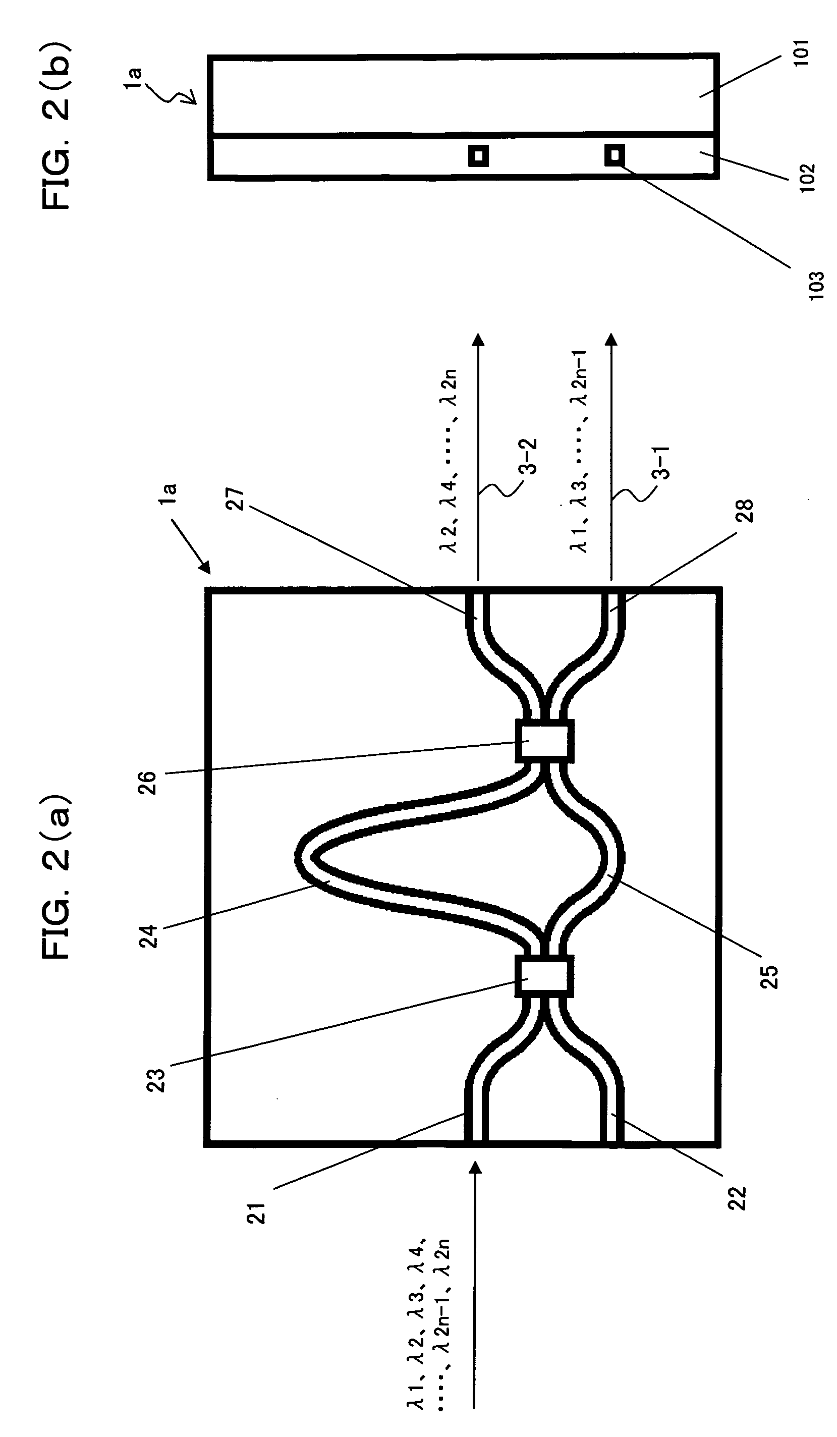
[0081] [A-11] Light Dividing Section 1
[0082] The light dividing section 1 is capable of dividing wavelength spectrum with respect to the wavelength-division multiplexed light beam, which is inputted via the optical fiber 60, and outputting the same as a plurality (2 in this case) of divided light beams 3-1 and 3-2, which have...
second embodiment
[B] Description of Second Embodiment
[0182] [B-11] Configuration
[0183]FIG. 23 and FIG. 24 show an optical device 200 according to a second embodiment of the present invention. As shown in FIG. 23 and FIG. 24, the optical device 200 according to the second embodiment includes a light dividing section 1, a first lens 61, a diffraction grating 2 and a second lens 62, which are the same as those in the above-described optical device 100 according to the first embodiment. However, the optical device 200 is different from the optical device 100 in a point that photo electric transfer elements 7d-1 to 7d-n corresponding to the number of second wavebands constituting multiplexed wavelength spectrum portion; that is, the number (n) of wavelength-separated light beams 6-1 to 6-n are included.
[0184] The photo electric transfer elements 7d-1 to 7d-n constitute optical elements that process the light beams constituting wavelength spectrum portions, which are spatially multiplexed by the wavelen...
third embodiment
[C] Description of Third Embodiment
[0227] [C-11] Configuration
[0228]FIG. 36 shows an optical device 300 according to a third embodiment of the present invention. The optical device 300 according to the third embodiment includes an optical module 100′, which is the same as the above-described optical device 100 according to the first embodiment. However, the optical device 300 is different from the optical device 100 in a point that the optical device 300 further includes a plurality of mirrors 7e-1 to 7e-n as optical elements of number corresponding to the number of second wavebands, which are the multiplexed wavelength spectrum portions; i.e., the number (n) of the wavelength-separated light beams 6-1 to 6-n, and a control section 90.
[0229] When an input light beam is inputted via the optical fiber 60, same as the case of the above described first embodiment, the optical module 100′ outputs the wavelength-separated light beams 6-1 to 6-n of the inputted light beam through the lig...
PUM
| Property | Measurement | Unit |
|---|---|---|
| wavelength | aaaaa | aaaaa |
| thickness | aaaaa | aaaaa |
| thickness | aaaaa | aaaaa |
Abstract
Description
Claims
Application Information
 - R&D
- Intellectual Property
- Life Sciences
- Materials
- Tech Scout
- Unparalleled Data Quality
- Higher Quality Content
- 60% Fewer Hallucinations
Browse by: Latest US Patents, China's latest patents, Technical Efficacy Thesaurus, Application Domain, Technology Topic, Popular Technical Reports.
© 2025 PatSnap. All rights reserved.Legal|Privacy policy|Modern Slavery Act Transparency Statement|Sitemap|About US| Contact US: help@patsnap.com