Radio communication apparatus

a radio communication and apparatus technology, applied in the field of radio communication apparatus, can solve the problems of limited digital processing units, unrealistic limitations, and limitation of the sampling frequency fs of da and ad conversion, and achieve the effect of increasing the number of carriers and increasing the sampling frequency

Inactive Publication Date: 2006-05-18
FUJITSU LTD
View PDF2 Cites 31 Cited by
  • Summary
  • Abstract
  • Description
  • Claims
  • Application Information

AI Technical Summary

Benefits of technology

[0028] Accordingly, an object of the present invention is to provide a radio communication apparatus in which the number of carriers can be increased while an increase in sampling frequency necessary for AD conversion and the like is suppressed.

Problems solved by technology

With the arrangement of FIG. 5, a problem which arises is that when it is attempted to increase the number of carriers, there is a limitation upon the digital processing units, especially upon the sampling frequency Fs of the DA and AD conversions.
The problem which arises is that this is not realistic.
The prior art of FIG. 5 is such that if an attempt is made to increase the number of carriers, a problem which arises is that there is a limitation upon the sampling frequency Fs of the DA and AD conversions.
The number of carriers that can be added on is limited by this limitation on the sampling frequency.
Further, this prior art does not eliminate intermodulation distortion produced when multicarriers are divided into two systems, namely systems on low- and high-frequency sides, and outputs of transmit amplifiers in transmitting units provided in respective ones of the systems are directly coupled.

Method used


Image

  • Radio communication apparatus
  • Radio communication apparatus
  • Radio communication apparatus

Examples


first embodiment

(B) First Embodiment

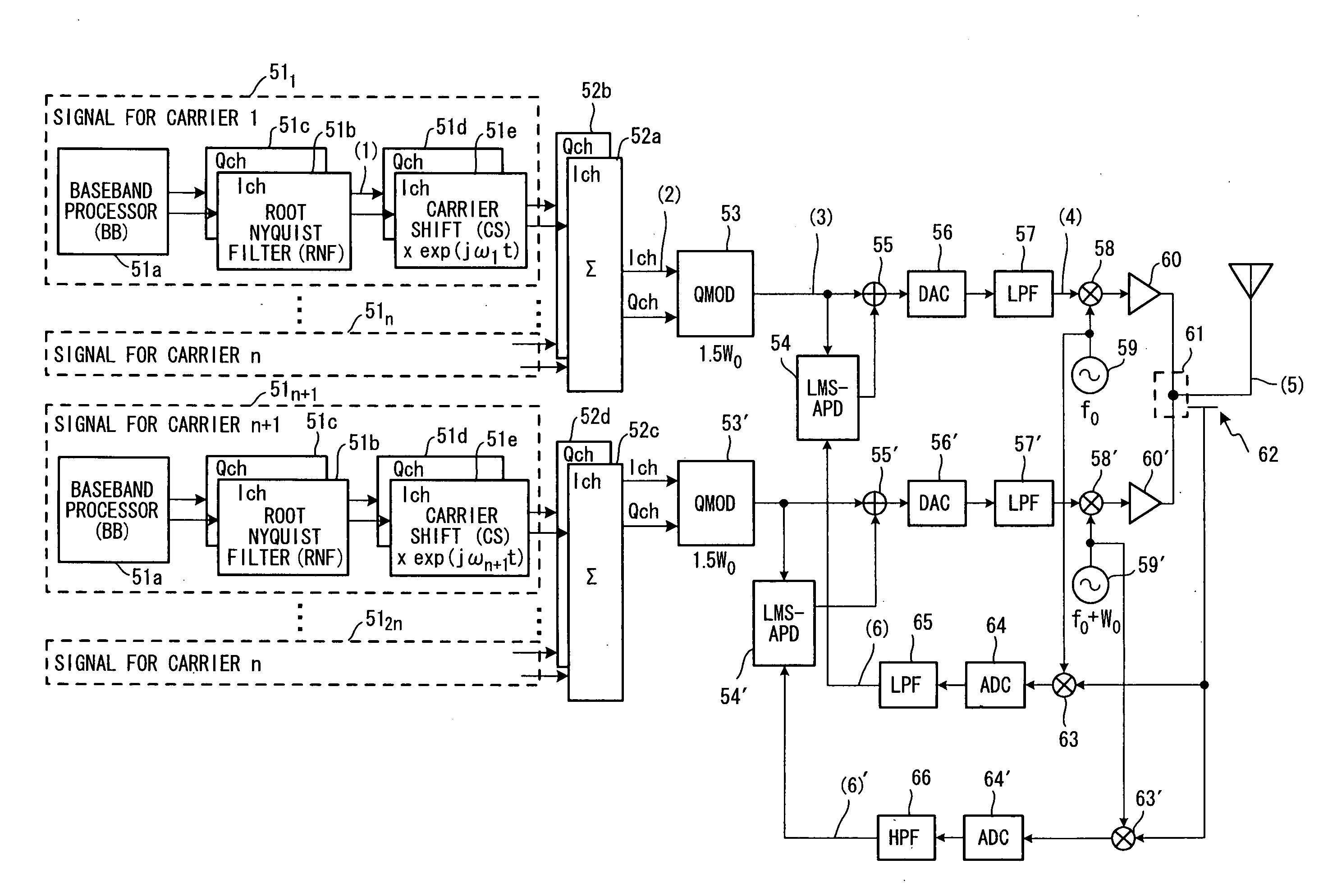
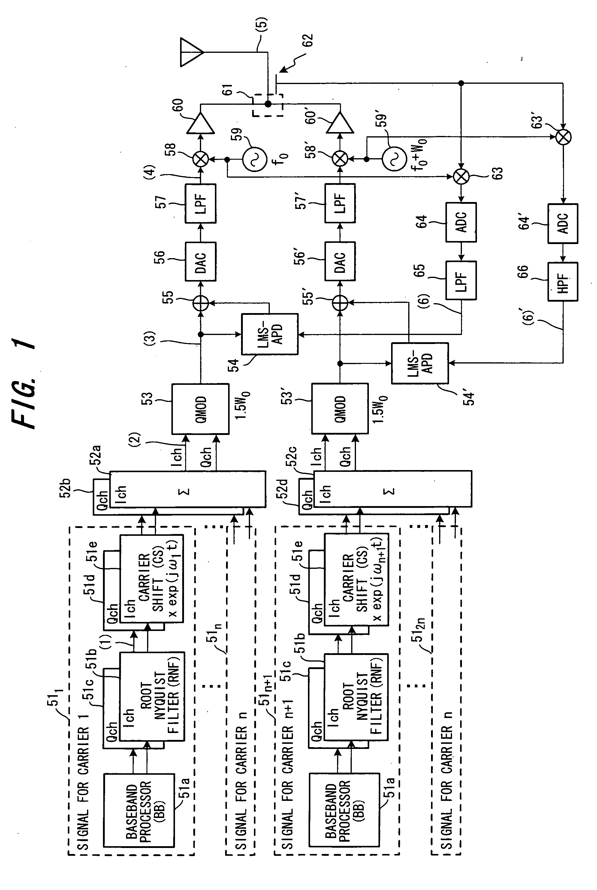
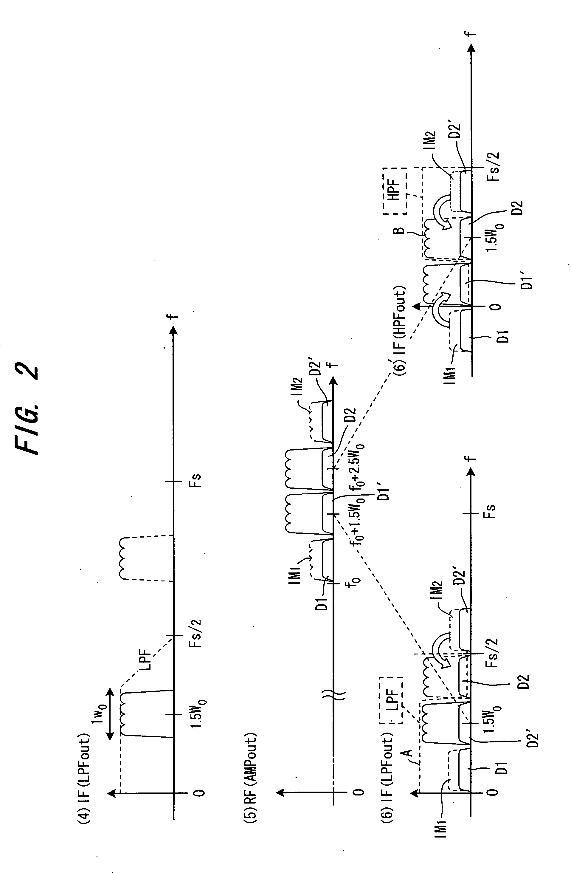
[0051]FIG. 1 is a block diagram of a radio communication apparatus according to a first embodiment of the present invention. FIG. 2 is a diagram useful in describing the operation of this apparatus, in which (4) to (6)′ illustrate spectrums associated with portions identified by the same numbers in FIG. 1. Since the spectrums (1) to (3) in FIG. 2 are identical with those of the example of the prior art, these are not illustrated here (see FIG. 6).

[0052] A plurality, i.e., 2n-number, of carriers are divided into two systems, namely n-number of carriers on the low-frequency side and n-number of carriers on the high-frequency side. A baseband processor (BB) 51a in each of signal processing units 511 to 51n provided for respective ones of the n carriers on the low-frequency side subjects data to be transmitted to baseband signal processing such as appending of error-correcting / detecting code, interleaving, multivalued modulation and code spreading and outputs a comp...

second embodiment

(C) Second Embodiment

[0063]FIG. 3 is a block diagram illustrating a radio communication apparatus according to a second embodiment of the invention. FIG. 4 is a diagram useful in describing the operation of this embodiment, in which (4) to (6)′ illustrate spectrums associated with portions identified by the same numbers in FIG. 3. Since the spectrums (1) to (3) in FIG. 4 are identical with those of the example of the prior art, these are not illustrated here. Components in FIG. 3 identical with those of the first embodiment in FIG. 1 are designated by like reference characters.

[0064] The embodiment of FIG. 3 differs from the first embodiment of FIG. 1 in the following respects:

[0065] (a) The transmit signal to which the distortion compensating signal has been added by the arithmetic units 55a, 55b is input to the quadrature modulators 53, 53′.

[0066] (b) Second mixers 71, 71′ and a local oscillator 72 for raising the frequency of the input signal by W0 are provided downstream of t...


PUM


Abstract

A plurality of carriers are divided into two systems, one on a low-frequency side and the other on a high-frequency side, a transmitting unit that executes processing for transmitting a signal wirelessly is provided in each of the two systems, and output lines of transmit amplifiers of each of the transmitting units are directly coupled and input to an antenna. A feedback unit on the low-frequency side feeds a low-frequency carrier signal portion contained in the transmit signal back to a distortion compensating unit on the low-frequency side, and a feedback unit on the high-frequency side feeds a high-frequency carrier signal portion contained in the transmit signal back to a distortion compensating unit on the high-frequency side. The distortion compensating units compensate for distortion on the low- and high-frequency sides.

Description

BACKGROUND OF THE INVENTION [0001] This invention relates to a radio communication apparatus and, more particularly, to a radio communication apparatus in which carriers are divided into two systems, namely high- and low-frequency systems, and which has a transmitting unit in each system that executes processing for transmitting a signal wirelessly, and a distortion compensating unit in each system that compensates for distortion produced by the transmitting unit. [0002] As the field of mobile communications systems has progressed, the quantity of signals that the radio communication apparatus is required to transceive has increased. With a multicarrier-type radio communication apparatus that transmits a number of adjacent carriers, the general approach is to increase the number of carriers to deal with an increase in quantity of transceive signals. [0003]FIG. 5 is a diagram illustrating the structure of a first multicarrier-type radio communication apparatus according to the prior ...

Claims


Application Information

Patent Timeline
Patent Type & Authority Applications(United States)
IPC IPC(8): H04B1/00H04B15/00
CPCH03F1/32H03F1/3247H03F1/3294H03F2200/111H03F2201/3206H04B1/0475H04B1/0483H04L27/368H04L27/2637
Inventor KODANI, MAYUMIFUNAKUBO, TOSHIAKI
Owner FUJITSU LTD
Why Eureka
Try Eureka