Steam distribution apparatus with removable cover for internal access

a technology of steam distribution apparatus and cover, which is applied in the direction of liquid cleaning, liquid/gas/vapor treatment of indefinite length materials, furnaces, etc., can solve the problem achieve the effect of reducing the likelihood of damage to the steam distribution apparatus, facilitating precise alignment of the sealable cleanout bar, and reducing the damage to the screen pla

Active Publication Date: 2006-05-25
HONEYWELL INTERNAITONL
View PDF14 Cites 10 Cited by
  • Summary
  • Abstract
  • Description
  • Claims
  • Application Information

AI Technical Summary

Benefits of technology

[0013] Typically, each discharge chamber has an associated access slot that is located adjacent to the outer, lower portion of the discharge chamber where debris tends to congregate. The dimensions of each access slot are preferably relatively small as compared to that of the discharge chamber. Upon removal of a cleanout bar or other resealable implement that covers the access slot, the internal parts of the discharge chamber the can be cleaned of debris, dirt, and other contaminants with high pressure water that is delivered by a spray wand configured to fit through the slot. This reduces the likelihood of damage to the steam distribution apparatus since the fragile screen plates are not removed and handled. The perimeter of each access slot can be lined with a gasket to provide additional protection against steam leakage. And to facilitate precise alignment of a sealable cleanout bar over the access slot, the housing adjacent the access slot and the cleanout bar itself can have matching apertures for visual alignment. These matching apertures can accommodate dowel pins which help secure the cleanout bar to the steam distributor body.
[0014] Furthermore, since the discharge screen plates are permanently secured onto the partitions that separate the discharge chambers, the screen plates are an integral part of the body structure of the steam distributor. This design further prevents the thin screen plates from being twisted or otherwise damaged. Preferably, the screen plates are welded onto the partitions so that under certain abnormal operating conditions such as steam overpressure within the discharge chambers, screen plate damage is significantly reduced because of the integral design.

Problems solved by technology

This reduces the likelihood of damage to the steam distribution apparatus since the fragile screen plates are not removed and handled.

Method used


Image

  • Steam distribution apparatus with removable cover for internal access
  • Steam distribution apparatus with removable cover for internal access
  • Steam distribution apparatus with removable cover for internal access

Examples


Embodiment Construction

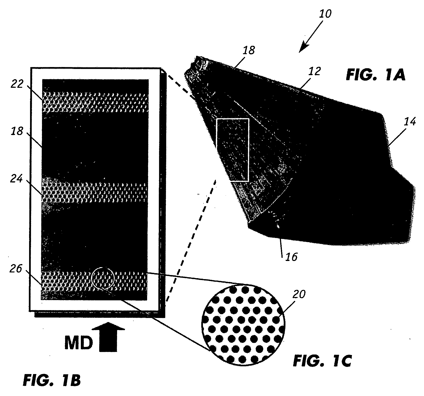
[0023]FIG. 1A illustrates the overall assembly of a steam distribution apparatus or steam shower 10 which includes an elongated housing 12 that is enclosed by end plates located at opposite ends. The length of the apparatus typically corresponds to the width of the sheet or web to which steam is to be applied. For papermaking operations the length can range, for instance, up to about 30 feet (9.1 meters). An external source of steam is connected to the steam distribution apparatus and excess steam in the form of condensate is removed through a drain 16 which is located on the side of end plate 14. The contour of the front screen panel or plate 18 preferably matches the external shape of the product to which steam is being supplied. The concave-shaped curvature of front screen panel 18 is particularly suited for apply steam to a roll of material. The front screen panel can also have a planar configuration to match the straight run of a moving sheet.

[0024] As further described herein...


PUM


Abstract

Employment of one or more resealable access slots in a steam distributor apparatus affords easy access to the internal chambers of the apparatus for cleaning and maintenance. The access slots can be located on the lower walls of the steam discharge chambers where debris tend to aggregate during operation of the apparatus. The apparatus can have multiple discharge chambers that are separated by spaced-apart partitions or baffle panels. Steam that is supplied from a steam header to each chamber exits each chamber through perforations of a discharge screen plate that is permanently secured onto adjacent partition panels. Actuators can regulate the steam flow from the steam header to the individual discharge chambers thereby creating a steam curtain with uniform or non-uniform cross direction profiles as desired.

Description

FIELD OF THE INVENTION [0001] The present invention generally relates to a steam distributor for applying steam to a paper sheet moving along its side wherein one or more sealable slots located along the cross direction of the distributor permits easy access to the internal compartments or chambers for cleaning and maintenance. BACKGROUND OF THE INVENTION [0002] The steam heating of a paper sheet is widely practiced in papermaking. The increase in sheet temperature that results provides increased drainage rates for the water thus reducing the amount of water to be evaporated in the drier section. Water drainage is improved by the application of steam principally because the heating of the sheet reduces the viscosity of the water, thus increasing the ability of the water to flow. Most of the heat transfer takes place when the steam condenses in the sheet. The condensation of the steam transforms the latent heat of the steam to sensible heat in the water contained by the sheet. [0003]...

Claims


Application Information

Patent Timeline
Patent Type & Authority Applications(United States)
IPC IPC(8): D06B5/02
CPCD21F7/008
Inventor PASSINIEMI, ERIC O.
Owner HONEYWELL INTERNAITONL
Why Eureka
Try Eureka