Device to attach a fuel return line to a fuel injector and device to suction fuel from a fuel injector

a technology of fuel injector and return line, which is applied in the direction of liquid fuel feeder, machine/engine, coupling, etc., can solve the problem of high installation force required to push the retaining clip, and achieve the effect of easy engagement and low production cos

Active Publication Date: 2006-05-25
COOPER STANDARD AUTOMATIVE INC
View PDF5 Cites 5 Cited by
  • Summary
  • Abstract
  • Description
  • Claims
  • Application Information

AI Technical Summary

Benefits of technology

[0036] In one aspect, the retaining means have locking tabs or locking slots and the retaining arms have locking slots or locking tabs. Such simply designed retaining means are inexpensive to produce, are easy to engage and are reliable, even over a long period, with respect to their engagement, the retaining force and any possible play.
[0037] In one aspect, the second housing part is provided with longitudinal guid

Problems solved by technology

Since the retaining clamp must not become detached from the fuel injector or loosen its seat during operation, it is seated relatively tightly on t

Method used


Image

  • Device to attach a fuel return line to a fuel injector and device to suction fuel from a fuel injector
  • Device to attach a fuel return line to a fuel injector and device to suction fuel from a fuel injector
  • Device to attach a fuel return line to a fuel injector and device to suction fuel from a fuel injector

Examples


Embodiment Construction

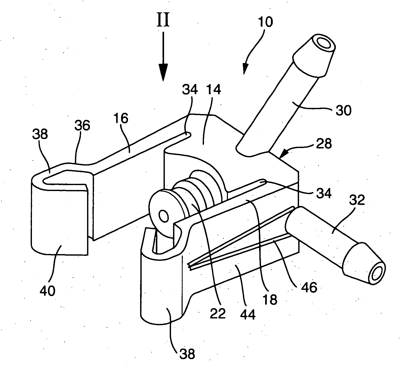
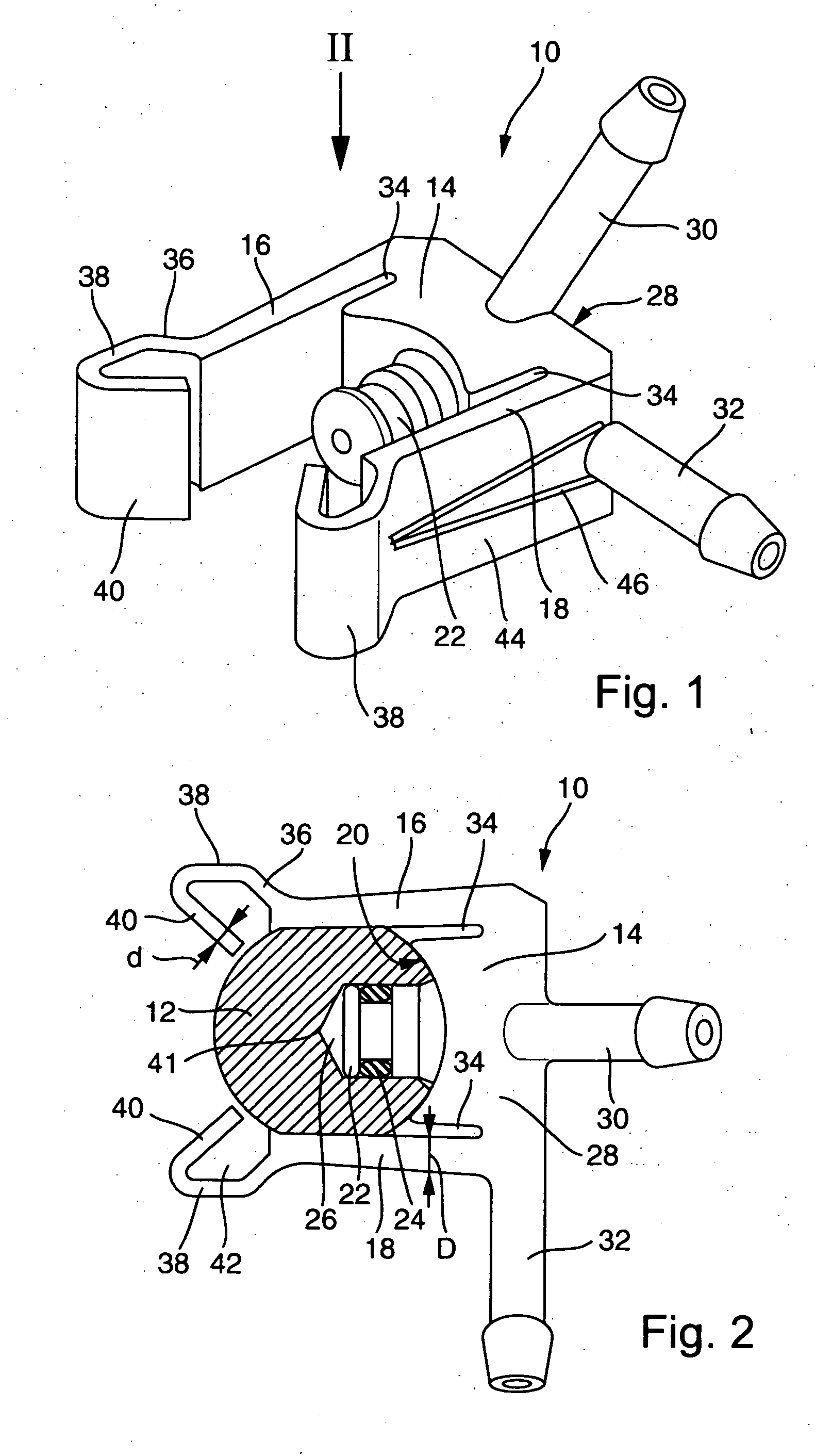
[0054]FIG. 1 shows a retaining device identified overall as 10 which can be attached to a fuel injector (see FIG. 2). The device 10 has a base 14 which is flanked on both sides by retaining arms 16 and 18. On the side facing the fuel injector 12, the base 14 has a concavity 20 which abuts the jacket of the fuel injector 12 when the retaining device 10 is installed. A connector 22, which is sealed by an O-ring 24 and sits in a return passage 26 for the fuel injector 12, projects radially from the concavity 20. The excess fuel from the fuel injector 12 is taken through this return passage 26 from the fuel injector 12 and to the connector 22.

[0055] The base 14 and the two retaining arms 16 and 18 form a main body 28 from which two connecting fittings 30 and 32 project onto which fuel return lines leading to the tank can be installed. The connecting fittings 30 and 32 are electrically connected to the connector 22 so that the excess fuel can drain through the connecting fittings 30 or ...


PUM

PropertyMeasurementUnit
Thicknessaaaaaaaaaa
Pressureaaaaaaaaaa
Areaaaaaaaaaaa

Abstract

A device to suction fuel from a fuel injector and a device to attach a fuel return line to a fuel injector with a C-shaped main body partially encircling the fuel injector having two retaining arms which abut the fuel injector and grip it from the back at least to a small degree, with a connector coacting with a drain passage of the fuel injector and at least one connecting fitting for the fuel return line. The connecting fitting and the connector are electrically connected. The free ends of the retaining arms have a first section in which they are angled towards each other and towards the base of the main body.

Description

BACKGROUND [0001] It is known that fuel injectors are provided with fuel return lines through which the fuel which is not consumed at the fuel injector is returned to the tank. The fuel injector provides a drain passage for this purpose to which a connector for a retaining clamp can be attached. The retaining clamp for its part possesses a connecting fitting for the fuel return line. In this way, the excess fuel can be drawn off to the tank. [0002] The retaining clamp is designed as a self-locking clip and has two retaining arms which partially encircle the fuel injector. Since the retaining clamp must not become detached from the fuel injector or loosen its seat during operation, it is seated relatively tightly on the fuel injector, which has the disadvantage that relatively high installation force is necessary to push the retaining clip onto the fuel injector. [0003] Furthermore, devices for generating negative pressure by utilizing the venturi principle are sufficiently known. A ...

Claims


Application Information

Patent Timeline
IPC IPC(8): F02M55/02
CPCF02M55/002F02M55/004F02M2200/803F04F5/10F04F5/44F04F5/46F16L37/008F16L47/32
Inventor HOUY, SYLVAINSAXER, DANIELVIERNEISEL, THOMASKORNATZ, YANARENDT, VALERIHACKEL, ANDRESTUHLDREIER, DETLEF
Owner COOPER STANDARD AUTOMATIVE INC
Why Eureka
Try Eureka