Axle unit with slip sensor and slip meansurement method

a technology of axle unit and a sensor, which is applied in the direction of pedestrian/occupant safety arrangement, instruments, tractors, etc., to achieve the effect of good accuracy and more appropriate control of the stable running of the vehicl

Inactive Publication Date: 2006-05-25
NSK LTD
View PDF2 Cites 39 Cited by
  • Summary
  • Abstract
  • Description
  • Claims
  • Application Information

AI Technical Summary

Benefits of technology

[0024] According to the invention, the wheel slip ratio and the slip state can be found with go

Problems solved by technology

Consequently, there is a problem of incapability of precisely finding the sli

Method used


Image

  • Axle unit with slip sensor and slip meansurement method
  • Axle unit with slip sensor and slip meansurement method
  • Axle unit with slip sensor and slip meansurement method

Examples


application example 1

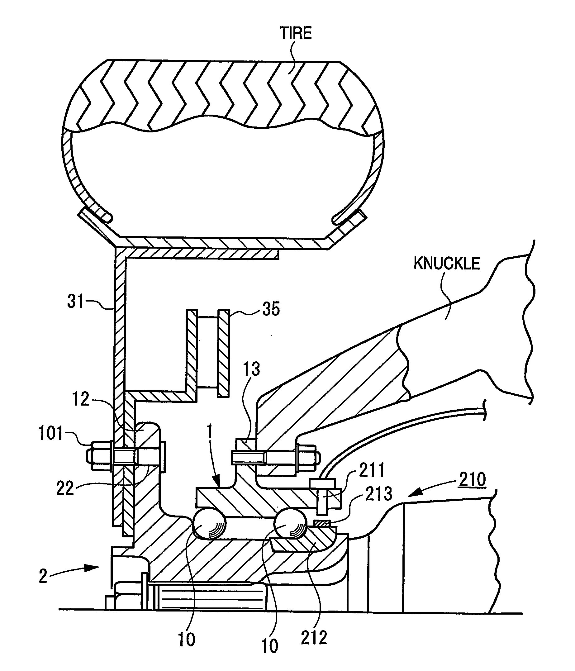
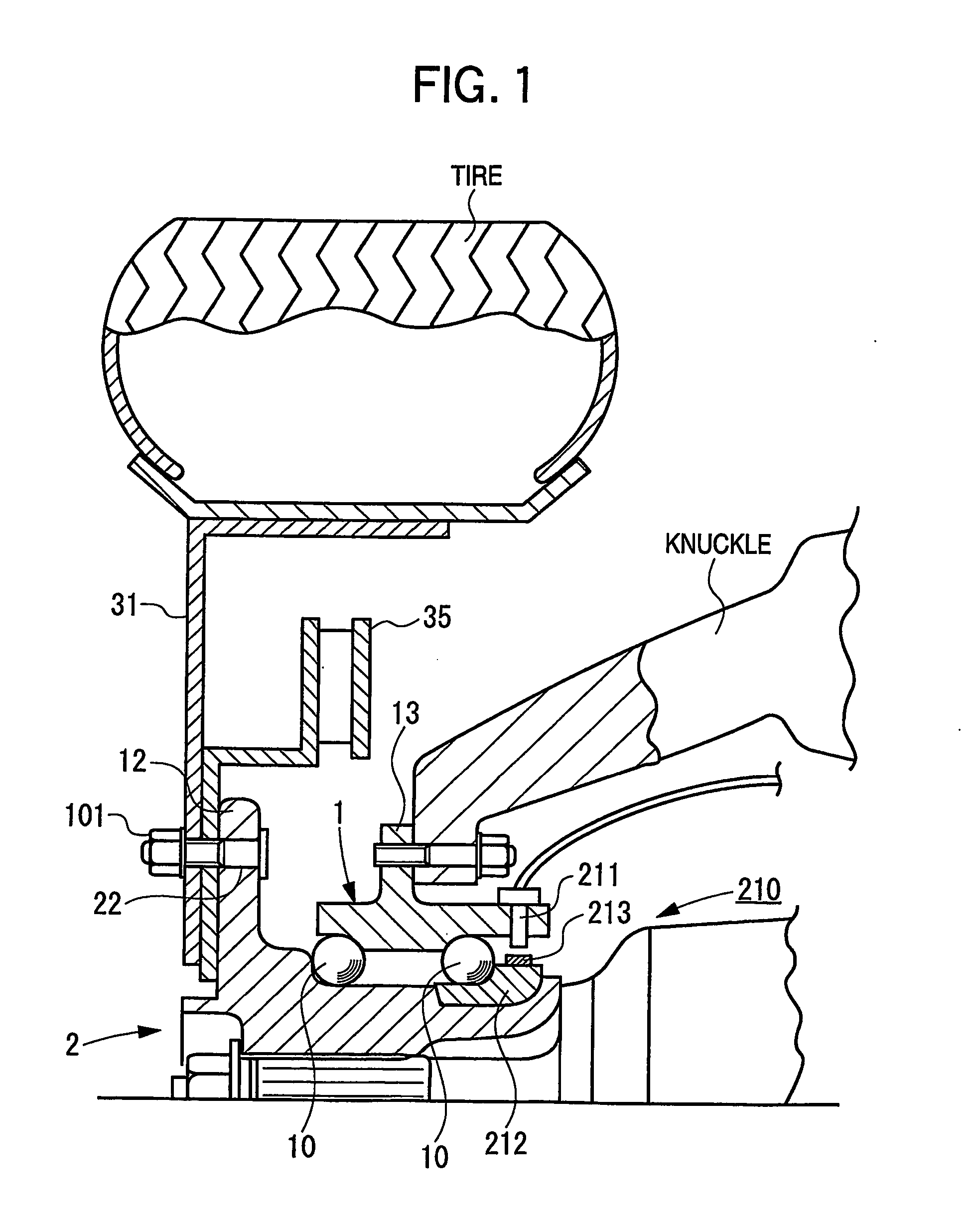
[0382] A wheel slip measurement method of using an acceleration sensor and a wheel rotation sensor, attached to each axle unit of a vehicle and combining the number of revolutions detected by the rotation sensor and the acceleration detected by the acceleration sensor to find a slip state of the axle unit.

application example 2

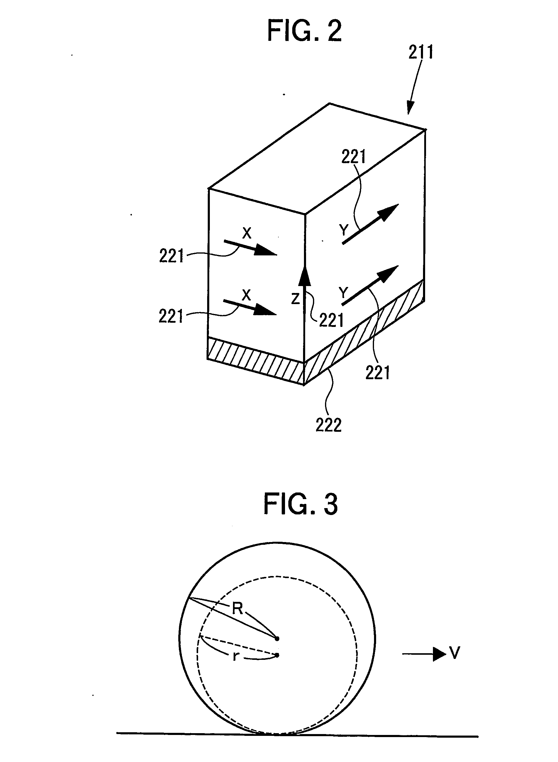
[0383] A method of using an acceleration sensor in the traveling direction of each wheel and a wheel rotation sensor, attached to each axle unit of a vehicle and combining rotation angular speed ω detected by the rotation sensor and acceleration α detected by the acceleration sensor to find ground speed V of each wheel according to V=(α / ωα)·ω.

application example 3

[0384] A method in application example 2 wherein as the acceleration, for an acceleration sensor using a force produced by acceleration and measuring the acceleration, true acceleration α is found according to α=αa+g sinβ using output αa of the acceleration sensor, road surface gradient angle β, and gravity acceleration


PUM


Abstract

An axle unit 210 including a rolling bearing unit attached to a knuckle of a wheel support member has a slip sensor (211) including acceleration sensors and a rotation sensor in one piece. The slip sensor (211) has the rotation sensor placed on the base face, and the rotation sensor is placed facing an encoder (213) attached to a rotation member (212). At the vehicle running time, the traveling acceleration in the traveling direction of the wheel and the rotation angular speed are detected and at the vehicle running time, the ground speed of each wheel, the tire radius of each wheel, and the slip ratio of each wheel are found.

Description

TECHNICAL FIELD [0001] This invention relates to an axle unit with a slip sensor and a slip measurement method used for stability control (stable run control) of an automobile. BACKGROUND ART [0002] In recent years, a stability control system is adopted for a vehicle (for example, refer to patent document 1). Thus, a slip sensor for measuring the slip ratio and the slip state for each axle with high accuracy is demanded. A method for measuring the condition required for stability control using the slip sensor is demanded. (The slip ratio represents the difference between the peripheral speed of tire and the travel speed (ground speed) of tire. Generally, it is said that the slip ratio becomes 0.001, 0.01, 0.1, etc., because of a partial slip even when the tire grips the ground.) [0003] [Patent document 1] JP-A-2003-118554 DISCLOSURE OF THE INVENTION [0004] By the way, the slip ratio of each wheel needs to be measured with good accuracy to enhance the control accuracy of TCS, ABS, st...

Claims


Application Information

Patent Timeline
IPC IPC(8): G01P1/02F16C41/04B60T8/171B60T8/32G01P3/44
CPCB60T8/171B60T8/329G01P3/443
Inventor ISHIKAWA, HIROAKINAKAGOME, YOSHIFUMI
Owner NSK LTD
Why Eureka
Try Eureka