Resistance welding tip with improved cooling system

a cooling system and welding tip technology, applied in the direction of cooled electrodes, auxillary welding devices, soldering apparatus, etc., can solve the problems of cap changing configuration, premature deformation and failure, transfer of significant heat energy to the cap, etc., to facilitate the proper placement of the cooling system, increase the temperature decay rate of the welding device, and increase the rate

Active Publication Date: 2006-05-25
GM GLOBAL TECH OPERATIONS LLC
View PDF4 Cites 4 Cited by
  • Summary
  • Abstract
  • Description
  • Claims
  • Application Information

AI Technical Summary

Benefits of technology

[0011] A fourth aspect of the present invention concerns a method for increasing the temperature decay rate of a welding device having a structural component and a first engaging component removably attached to the structural component. The method comprises the steps of adjustably connecting a cooling system including a supply tube defining an outlet to the structural component, fixing the outlet in a first position, so that the system is configured to withdraw heat energy from the first engaging component at a first rate, and adjusting the outlet to a second configuration, so as to increase the rate, without disconnecting the system from the structural component.
[0012] It will be understood and appreciated that the present invention provides a number of advantages over the prior art, including, for example, providing an adjustable connection to the welding device that facilitates the proper placement of the cooling system. Using an adjustable connection also reduces down time and costs associated with dismantling and repositioning conventional cooling systems.

Problems solved by technology

The proximity of the welding cap to the source of heat results in the transfer of significant amounts of heat energy to the cap.
This resultant heat absorption and excess cap temperatures causes premature deformation and failure.
This tendency further causes the cap to change its configuration and reduces its efficiency.
Where this distance is not properly set, inefficiency concerns arise and, at worst, the cooling system is rendered ineffective.
To cure improper distancing or placement, the system must be dismantled from the welding device and repositioned, which results in an inconvenience to the worker and costly down time to the entire process.

Method used


Image

  • Resistance welding tip with improved cooling system
  • Resistance welding tip with improved cooling system
  • Resistance welding tip with improved cooling system

Examples


Embodiment Construction

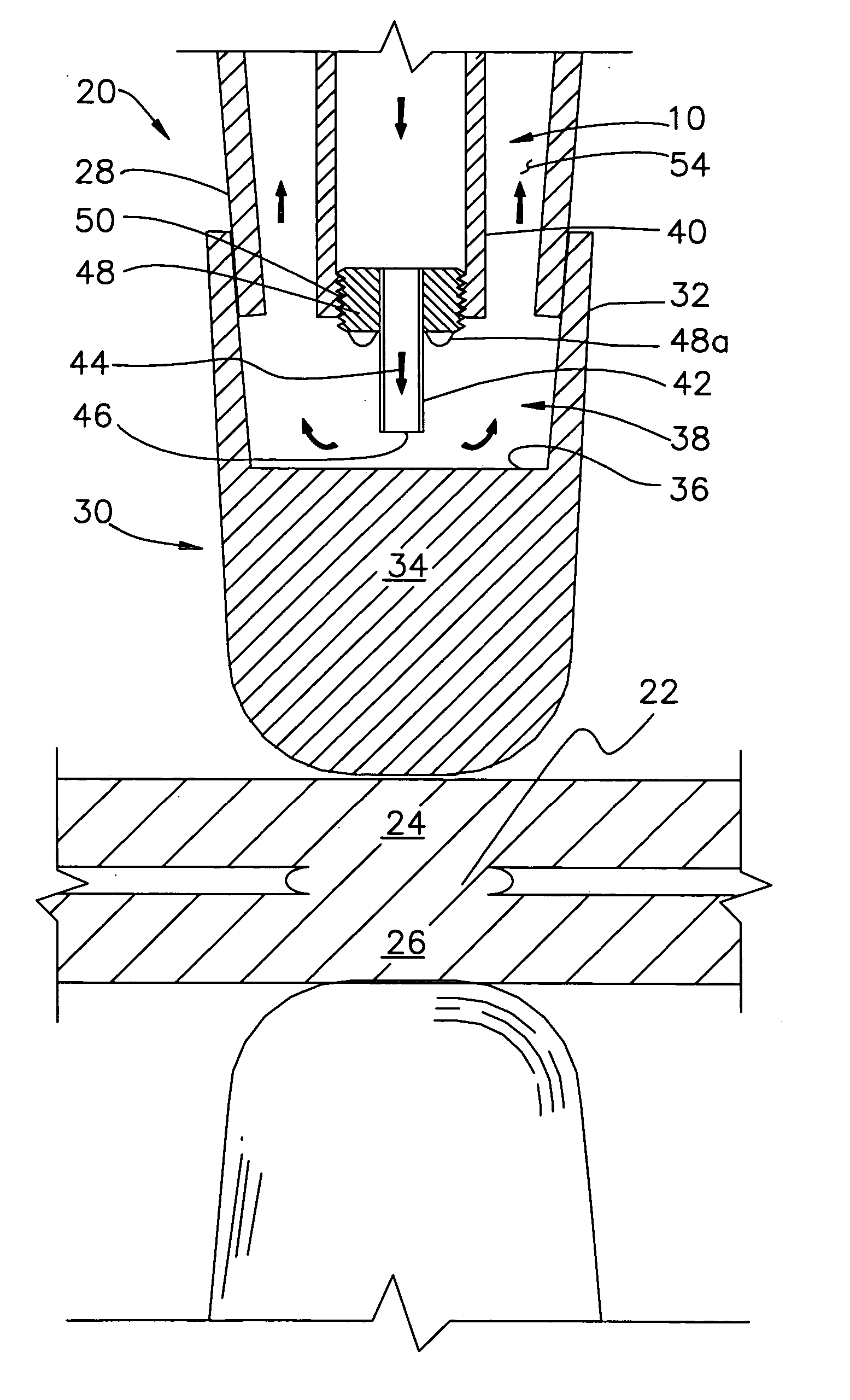
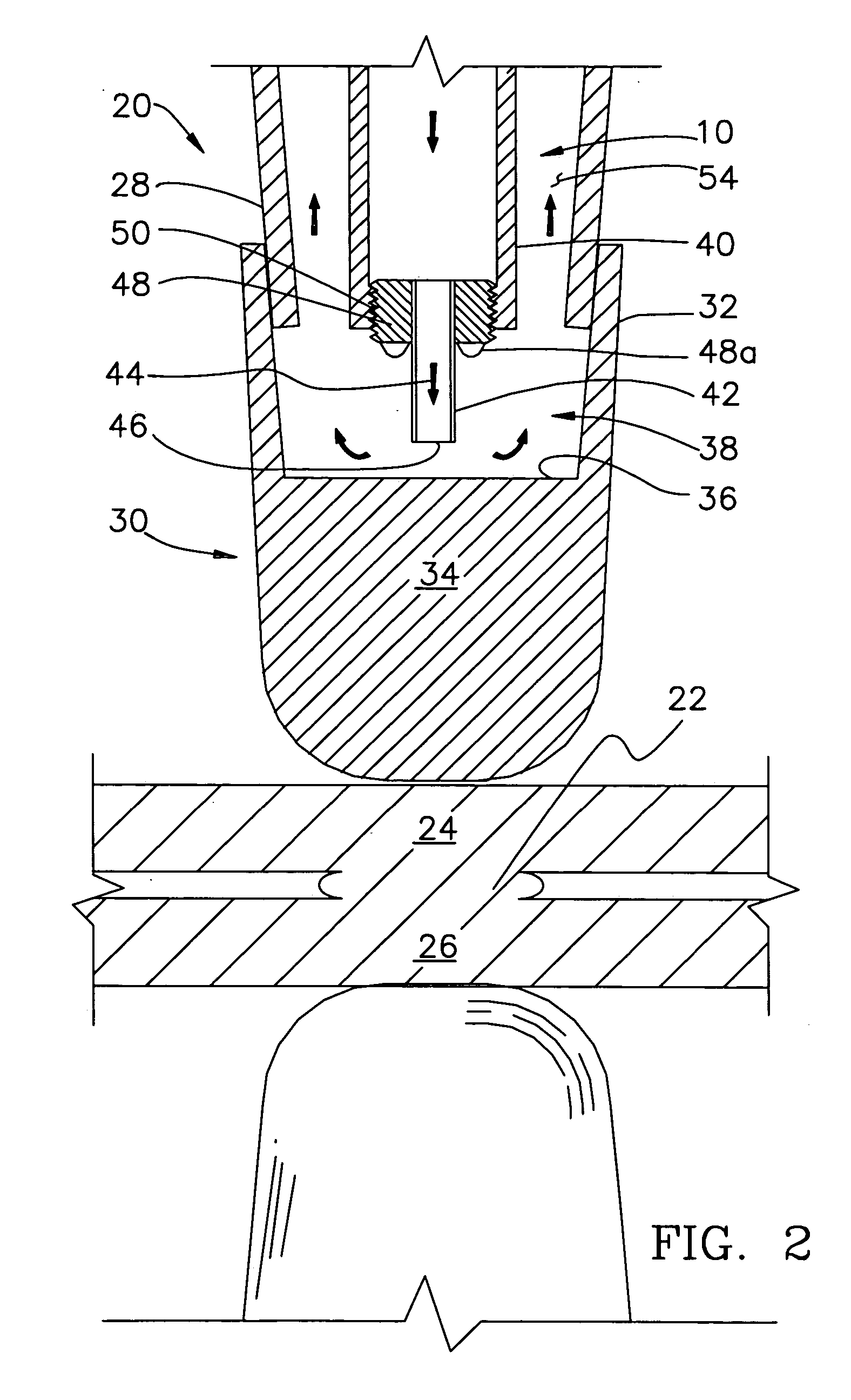
[0024] The present invention concerns an improved cooling system 10 for adjustably adapting to a two-component spot-welding electrode device 12. The cooling system 10 is thermally coupled to the welding device 12, i.e. when operative it is able to effect a greater than 5% change in the temperature decay rate of at least a portion of the device 12 in comparison to passive approaches. It should initially be noted, however, that the improved cooling system 10, is not limited in use to the welding device shown and described herein, and can be utilized with other suitable configurations.

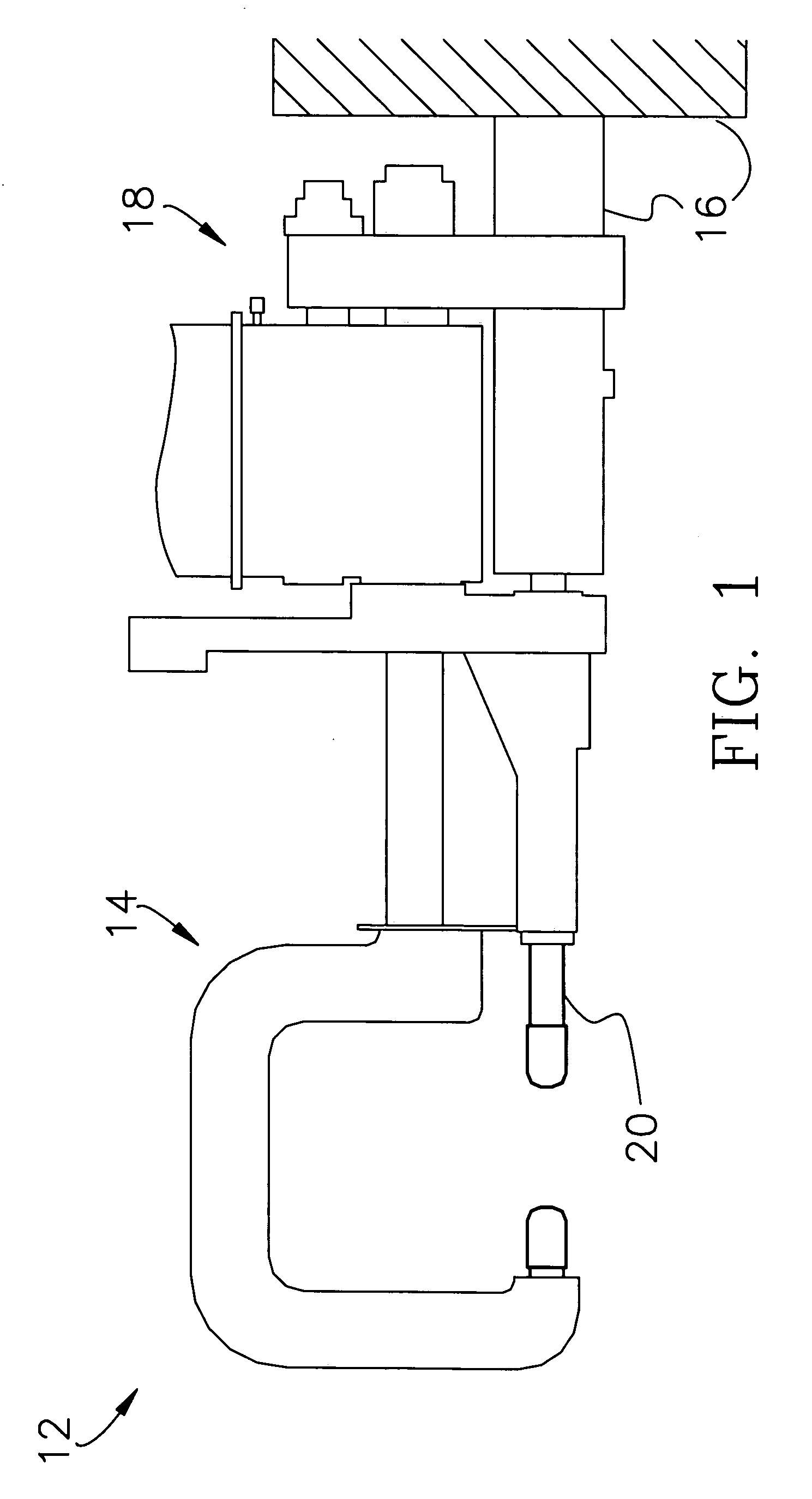
[0025] As shown in FIG. 1, the welding device 12 typically includes a welding gun 14, a structural base 16, electrical and mechanical apparatus 18 for maneuvering the gun 14 to a desired location, and at least one electrode 20 removably attached to the gun 14. Shown in FIG. 1 is a press weld system having upper and lower electrodes. The upper and lower electrodes are identical in structure and function, ...


PUM

PropertyMeasurementUnit
distanceaaaaaaaaaa
pressureaaaaaaaaaa
temperaturesaaaaaaaaaa

Abstract

An improved cooling system for adapting to a two-component welding electrode device having a shank and cap, includes a retractable nozzle tube, a manifold, and an adjustment element for adjustably interconnecting the tube and manifold. A threaded bushing or plunger is attached to the tube and operable to adjust the distance between the interior surface of the cap and the outlet of the tube to a preferred distance. A threaded sleeve interconnects the tube and bushing for additional adjustability. The tube defines an elastically compressible bellows section, and a spacer is removably attached to the distal end of the tube for automatic adjustment of the outlet position by the cap.

Description

BACKGROUND OF THE INVENTION [0001] 1. Field of the Invention [0002] The present invention relates to resistance welding devices, and more particularly to a two-component electrode device having an improved cooling configuration. [0003] 2. Discussion of Prior Art [0004] Two-component electrode welding devices are used in various industrial applications, including automotive assembly. These devices typically include a conductive shank removably connected to a welding gun, and a conductive welding cap removably connected to the distal end of the shank. As is well known in the art, these devices function to transmit electric currents through adjacently placed subject members, so that the resistance of the subject members generates sufficient heat energy to produce a spot weld therebetween. The proximity of the welding cap to the source of heat results in the transfer of significant amounts of heat energy to the cap. This resultant heat absorption and excess cap temperatures causes prema...

Claims


Application Information

Patent Timeline
Patent Type & Authority Applications(United States)
IPC IPC(8): B23K11/30
CPCB23K11/3054
Inventor STEVENSON, ROBINWANG, PEI-CHUNG
Owner GM GLOBAL TECH OPERATIONS LLC
Why Eureka
Try Eureka