Laser power control with automatic compensation

a technology of automatic compensation and power control, applied in the direction of optical radiation measurement, instruments, semiconductor lasers, etc., can solve the problems of numerous temperature variations, remote and difficult to reach, and inability to accurately control the operation of the device,

Active Publication Date: 2006-05-25
MACOM TECH SOLUTIONS HLDG INC
View PDF6 Cites 9 Cited by
  • Summary
  • Abstract
  • Description
  • Claims
  • Application Information

AI Technical Summary

Benefits of technology

[0008] To overcome the drawbacks of the prior art, a method and apparatus is disclosed for optic signal power control to maintain a desired or optimum optic signal power level. During start-up, a default or target value from memory may be utilized to bias or otherwise control operation of an optic signal generator or driver. During operation, pre-stored values may continue to be utilized or an open loop or closed loop control system may be utilized. An open loop control system may incorporate a temperature module or a timer module to account for changes in envir...

Problems solved by technology

Examples include optical communication systems, which may operate in remote locations or small and crowded equipment rooms and computer rooms, optical media readers found in automobiles and home environments, as well as optical systems in remote industrial applications which are remote and difficult to reach.
The varying environmental aspects of these varying locations present numerous hurdles for accurate device operation.
One such hur...

Method used


Image

  • Laser power control with automatic compensation
  • Laser power control with automatic compensation
  • Laser power control with automatic compensation

Examples


Embodiment Construction

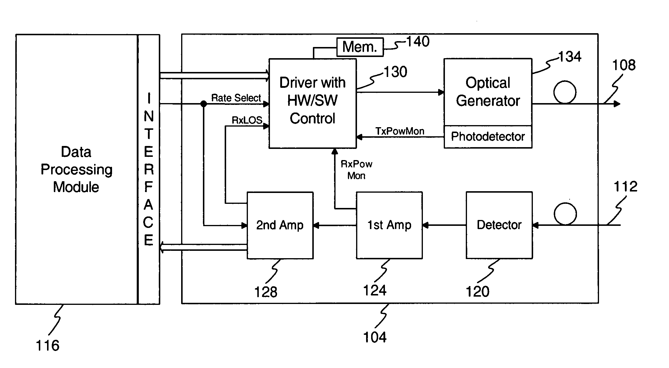
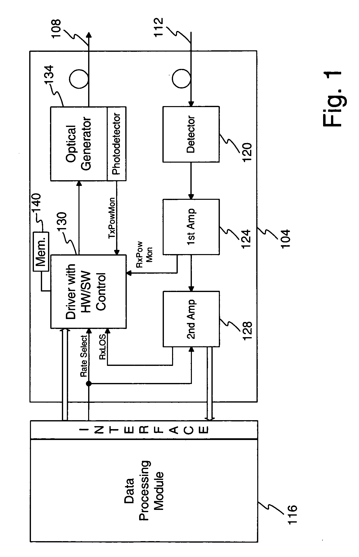
[0032] The method and apparatus disclosed herein overcomes the drawbacks of the prior art and provides additional advantages, features, and benefits. In general, an optical communication system is described herein as an example environment for the method and apparatus described herein. Although described in connection with an optical communication system, other environments that would benefit from the methods and apparatus described herein, such as, but are not limited to, optical media drives, laser surgery equipment, laser welding, free-space optical links and any other environment that utilizes an optical device.

[0033] Turning now to FIG. 1, a block diagram of an example module for an optical communication system is shown. The configuration shown in this Figure, and the other Figures provided herein, is but one possible configuration and, as such, it is contemplated that one of ordinary skill in the art may arrive at a different embodiment, configuration, or method of operation ...


PUM


Abstract

A method and apparatus is disclosed for optic signal power control to maintain a desired or optimum optic signal power level. During start-up, a target value from memory may be utilized to control one or more power levels of an optic signal. There may comprise 2 or more different power levels for the optic signal. During operation, target values may continue to be utilized or an open loop or closed loop control system may be utilized. Compensation may occur for both additive noise/distortion and multiplicative noise/distortion. The compensation for one power level may be expanded or extrapolated to compensate for additive noise/distortion and multiplicative noise/distortion that affect other power levels.

Description

1. PRIOR APPLICATION DATA [0001] This application is a continuation-in-part of U.S. application Ser. No. 11 / 134,715 filed on May 20, 2005, which is a continuation-in-part of U.S. application Ser. No. 10 / 993,525 filed on Nov. 19, 2004.2. FIELD OF THE INVENTION [0002] The invention relates to optical signal generator output control and, in particular, to a method and apparatus for controlling optical signal generator output based on environmental or other factors. 2. RELATED ART [0003] Many modern electronic devices and systems utilize optical signals to achieve desired operation. Examples of such devices include fiber optic communication systems, optical media read and write devices in computer and home entertainment systems, such as CD players and DVD players, and other devices that utilize a laser, photodiode, or other optical device. [0004] As can be appreciated, these devices require highly precise operation and, with each generation of a product, a higher level of accuracy may b...

Claims


Application Information

Patent Timeline
IPC IPC(8): G01J1/32
CPCH01S5/0612H01S5/0617H01S5/06804H01S5/06832G01J1/32
Inventor DRAPER, DANIELREINTJES, MAURICE M.SADA, GILBERTO I.JONES, KEITH R.
Owner MACOM TECH SOLUTIONS HLDG INC
Why Eureka
Try Eureka