Pulse modulation light detection device, electronic apparatus, and pulse modulation light detection method

a detection device and light detection technology, applied in the direction of counting objects on conveyors, using reradiation, instruments, etc., can solve the problems of misdetection of objects a and b

Inactive Publication Date: 2006-05-25
SHARP KK
View PDF4 Cites 11 Cited by
  • Summary
  • Abstract
  • Description
  • Claims
  • Application Information

AI Technical Summary

Benefits of technology

[0017] The present invention is made in view of the foregoing problems, and its object is realizing a pulse modulation light detection device and a pulse modulation light detection method which can, even when external disturbing light exists, suppress malfunction caused by the external disturbing light, and realizing an electronic apparatus using the device and the method.
[0021] As a result, with the arrangement, only when signals are detected in at least two synchronization timings out of the plurality of synchronization timings, it is determined that synchronization occurs in one cycle. Therefore, even if random noise light such as external disturbing light from an inverter fluorescent lamp exists, and even if a light receiving signal derived from the external disturbing light overlaps with one of at least two synchronization timings, it is possible to reduce possibility that the light receiving signal overlaps with the other one of at least two synchronization timings. As such, it is possible to suppress misdetection caused by the external disturbing light.
[0024] With the method, it is detected whether an object exists or not based on the light receiving signal derived from the pulse lights having the two or more pulse intervals, and therefore it is possible to reduce misdetection of the object caused by random external disturbing light.

Problems solved by technology

However, in the conventional arrangement, there is a problem that although the object A to be detected does not exist, the output circuit 29 alternately outputs Hi and Lo due to external disturbing light as if oscillation occurs, and therefore the object A is misdetected.
Therefore, there is a problem that although the object A to be detected does not exist, the output circuit 29 alternately outputs Hi and Lo as if oscillation occurs, and accordingly the object A is misdetected.
There is a problem that when external disturbing light acting as noise is incident from the inverter fluorescent lamp illustrated in FIGS.

Method used


Image

  • Pulse modulation light detection device, electronic apparatus, and pulse modulation light detection method
  • Pulse modulation light detection device, electronic apparatus, and pulse modulation light detection method
  • Pulse modulation light detection device, electronic apparatus, and pulse modulation light detection method

Examples


Embodiment Construction

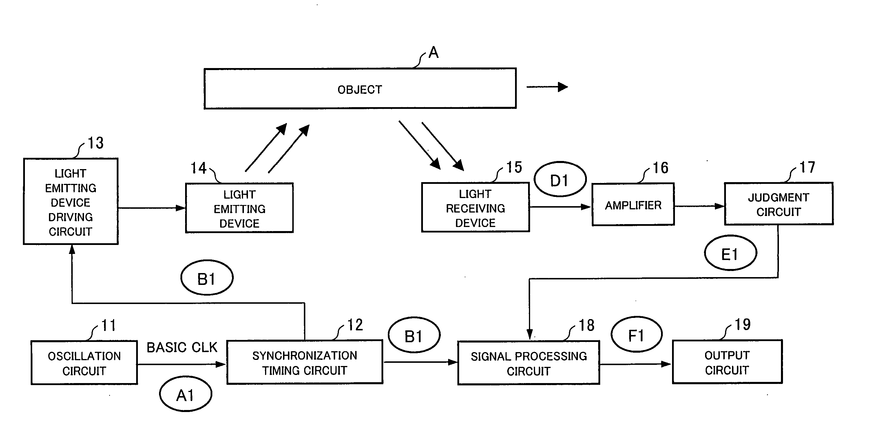
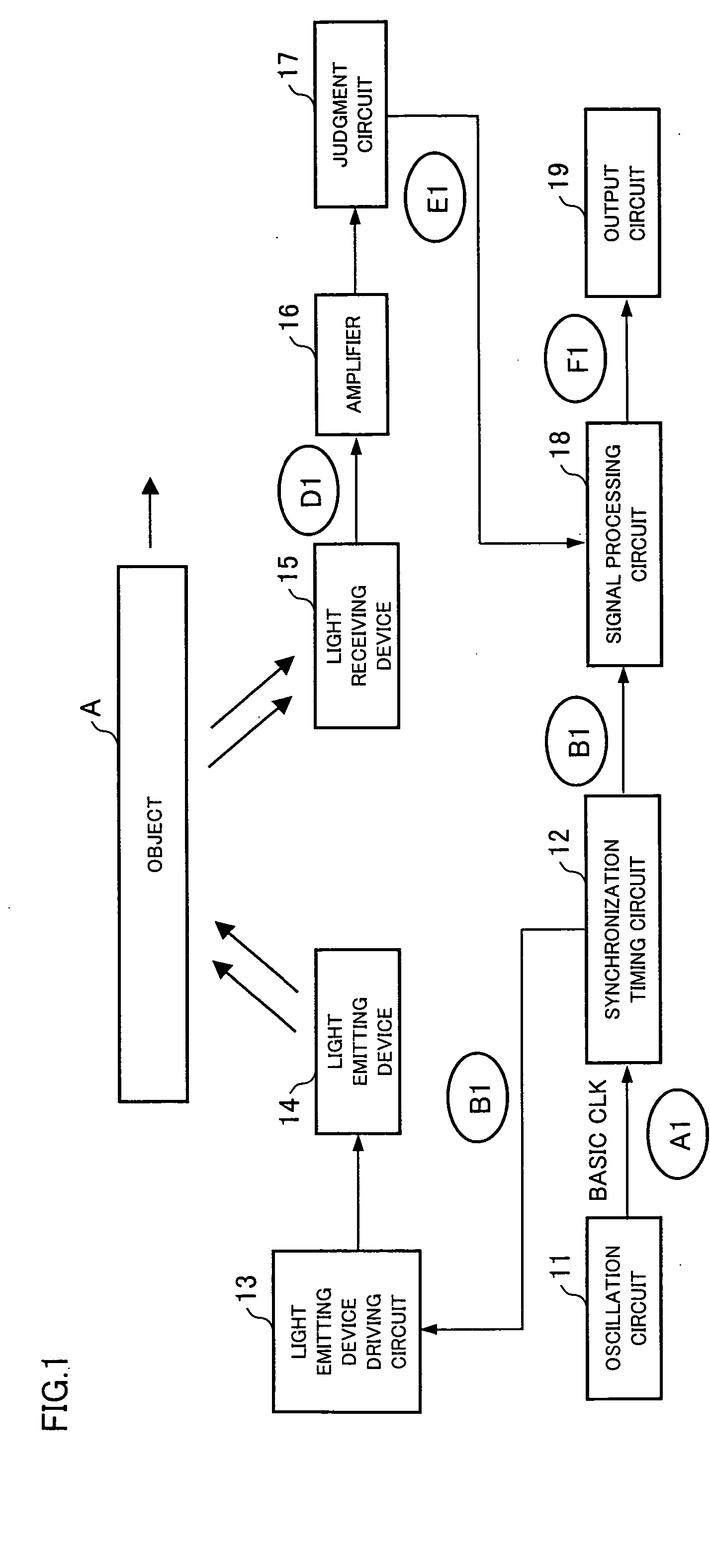
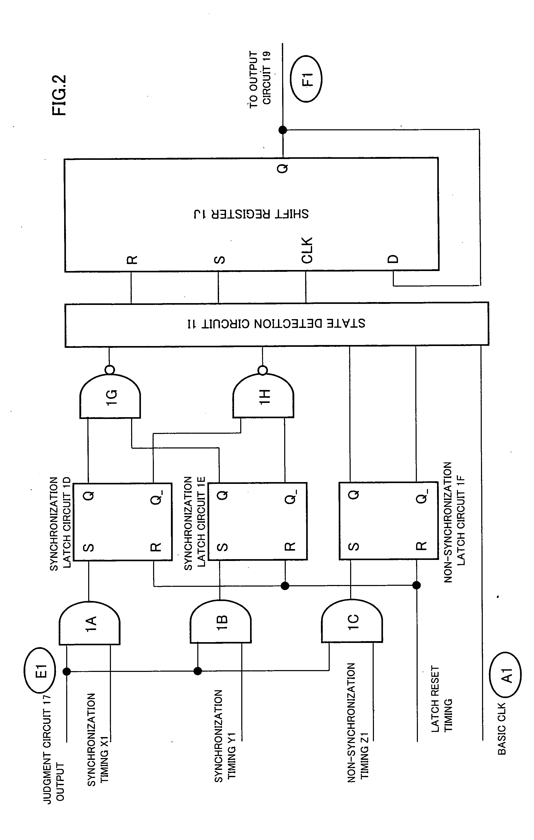
[0038] One embodiment of the pulse modulation light detection device and the pulse modulation light detection method according to the present invention is explained below with reference to FIGS. 1 through 5. As illustrated in FIG. 1, the pulse modulation light detection device of the present embodiment is provided with: an oscillation circuit 11 which has a crystal oscillator and the like, and generates and outputs a basic clock (abbreviated as CLK hereinafter) signal (A1) with a predetermined wavelength; and a synchronization timing circuit (pulse generating circuit) 12 for generating a light emitting timing pulse signal (B1) (pulse signal) based on the basic CLK signal.

[0039] Further, the pulse modulation light detection device is provided with: a light emitting device driving circuit 13 for generating a light emitting device driving signal corresponding to the light emitting timing pulse signal (pulse signal); and a light emitting device 14 for emitting, based on the light emitt...


PUM


Abstract

A light emitting device for emitting pulse lights synchronized with a pulse signal is provided. A light receiving device for receiving the pulse lights reflected by or penetrating an object to be detected is provided. A signal processing circuit for detecting whether the object exists or not, based on a light receiving signal from the light receiving device. A synchronization timing circuit for generating the pulse signal used for emitting a plurality of pulse lights in one cycle is provided. The signal processing circuit detects the plurality of pulses and outputs a detection signal for indicating whether the object exists or not.

Description

[0001] This non-provisional application claims priority under 35 U.S.C. § 119(a) on Patent Application No. 339117 / 2004 filed in Japan on Nov. 24, 2004, the entire contents of which are hereby incorporated by reference.FIELD OF THE INVENTION [0002] The present invention relates to a pulse modulation light detection device and a pulse modulation light detection method, by which a pulse-modulated light is emitted from a light emitting device and whether or not an object exists is detected. Particularly, the present invention relates to a pulse modulation light detection device and a pulse modulation light detection method which are suitable for electronic devices such as FA (Factory Automation) and OA (Office Automation) apparatuses (e.g. copying machines and printers), and amusement apparatuses which detect coins and balls. BACKGROUND OF THE INVENTION [0003] In electronic apparatuses such as FA and OA apparatuses (e.g. copying machines and printers), and amusement apparatuses (e.g. ga...

Claims


Application Information

Patent Timeline
Patent Type & Authority Applications(United States)
IPC IPC(8): G06M7/00
CPCG01S7/497G01S17/026G01S17/10G01S17/04
Inventor MARUYAMA, YASUHIRO
Owner SHARP KK
Why Eureka
Try Eureka