System for regulating the level of an amplified signal in an amplification chain

Inactive Publication Date: 2006-05-25
NXP BV
View PDF4 Cites 6 Cited by
  • Summary
  • Abstract
  • Description
  • Claims
  • Application Information

AI Technical Summary

Benefits of technology

[0033] This characteristic allows to easily va

Problems solved by technology

These regulating means exhibit a certain number of limitations.
Moreover, the use of such a peak amplitude detector is restrictive in that it does not allow the level of a SECAM-modu

Method used


Image

  • System for regulating the level of an amplified signal in an amplification chain
  • System for regulating the level of an amplified signal in an amplification chain
  • System for regulating the level of an amplified signal in an amplification chain

Examples


Embodiment Construction

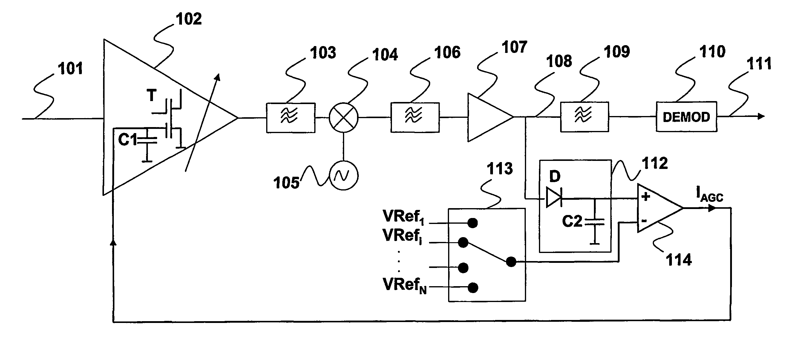
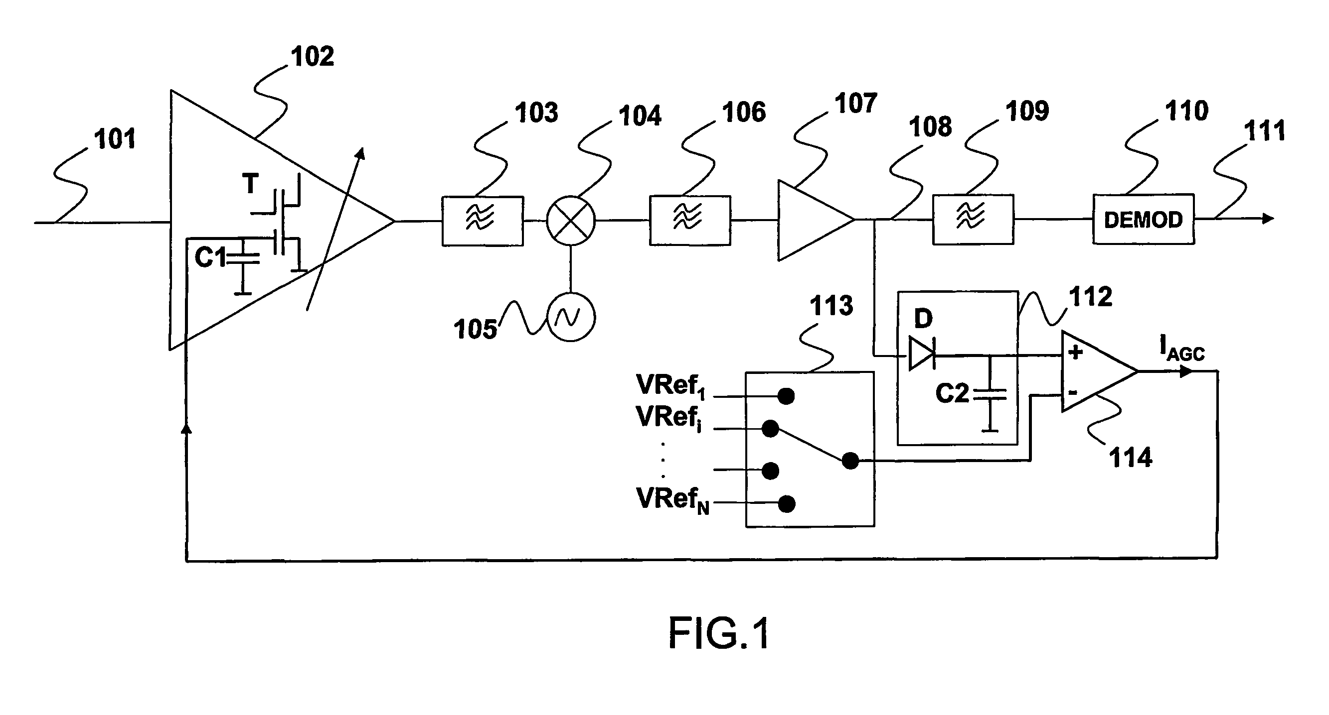
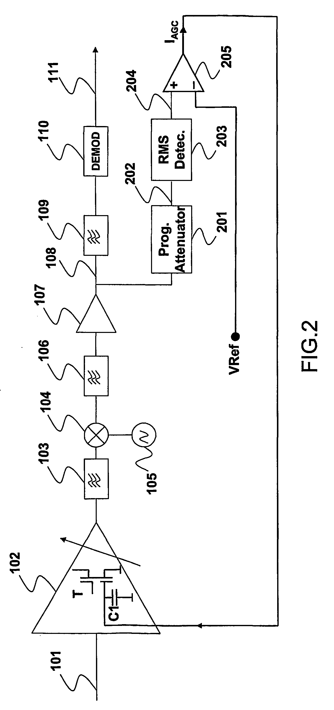
[0040]FIG. 2 shows a tuner comprising an amplification chain associated with a regulating system according to the invention. The amplification chain comprises the same elements as those described in relation to FIG. 1. The regulating system according to the invention comprises:

[0041] attenuation means 201 for generating an attenuated signal 202 from said amplified signal 108 according to a programmable attenuation factor,

[0042] conversion means 203 for converting said attenuated signal 202 in order to generate an output signal 204 intended to be compared with said reference level Vref.

[0043] A comparator 205 is used for comparing the output signal 204 and the reference level Vref. The comparator 205 generates an output current IAGC that is proportional to the difference between the level of the output signal 204 and the reference level Vref. The output of the comparator 205 is connected to the capacitor C1 of the amplifier 102 such that the current IAGC charges or discharges the ...


PUM


Abstract

This invention relates to a regulating system for regulating, with respect to a reference level (Vref), the level of an amplified signal (108), said regulating system comprising: -attenuation means (201) for generating an attenuated signal (202) from said amplified signal (108) according to a programmable attenuation factor, -conversion means (203) for converting said attenuated signal (202) in order to generate an output signal (204) intended to be compared with said reference level (Vref).

Description

FIELD OF THE INVENTION [0001] The invention relates to a regulating system for regulating, with respect to a reference level, the level of an amplified signal in an amplification chain. [0002] The invention has many applications, in particular in gain control systems that are used in tuners. BACKGROUND OF THE INVENTION [0003]FIG. 1 shows a tuner comprising an amplification chain associated with a regulating system that is known from the prior art. This tuner allows the reception and processing of a radio-frequency (RE) signal101 and comprises, arranged in series: [0004] a variable-gain amplifier 102 for amplifying the radio-frequency signal 101. The amplifier 102 comprises a MOSFET amplification transistor T connected to an integration capacitor C1, and the voltage level at the terminals of said integration capacitor C1 determining the gain of the transistor T, [0005] a selective filter 103 being dedicated to attenuate the image frequency and also the adjacent channels, [0006] a mix...

Claims


Application Information

Patent Timeline
IPC IPC(8): G05F1/56H03G3/30
CPCH03G3/3052
Inventor PRUVOST, XAVIERBRILLANT, JEROME
Owner NXP BV
Why Eureka
Try Eureka