Circuit breaker

Active Publication Date: 2006-05-25
MP HOLLYWOOD
View PDF11 Cites 16 Cited by
  • Summary
  • Abstract
  • Description
  • Claims
  • Application Information

AI Technical Summary

Benefits of technology

[0005] The invention relates to a novel U-shaped thermal sensing element to further alleviate causes of intermittent continuity during the application of low, open circuit voltage. The circuit breaker maintains the application of high contact force found in prior art designs, and incorporates a sliding contact motion applied during circu

Problems solved by technology

Because of the relatively high contact resistance associated with the two pairs of contacts utilized in these designs, they are susceptible to intermittent loss of electrical continuity for applications involving l

Method used


Image

  • Circuit breaker
  • Circuit breaker
  • Circuit breaker

Examples


Embodiment Construction

[0020] The present invention applies to push-to-reset and switchable breaker configurations, but only the push-to-reset breaker configuration is illustrated herein. The illustrated form should be considered to be a typical application but is not meant to restrict or limit the teaching to just that kind of circuit breaker.

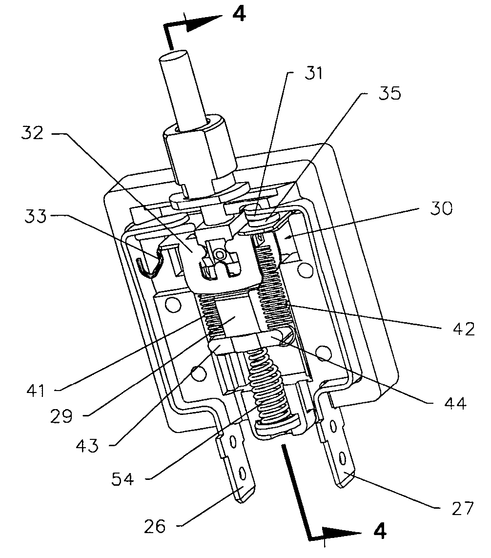
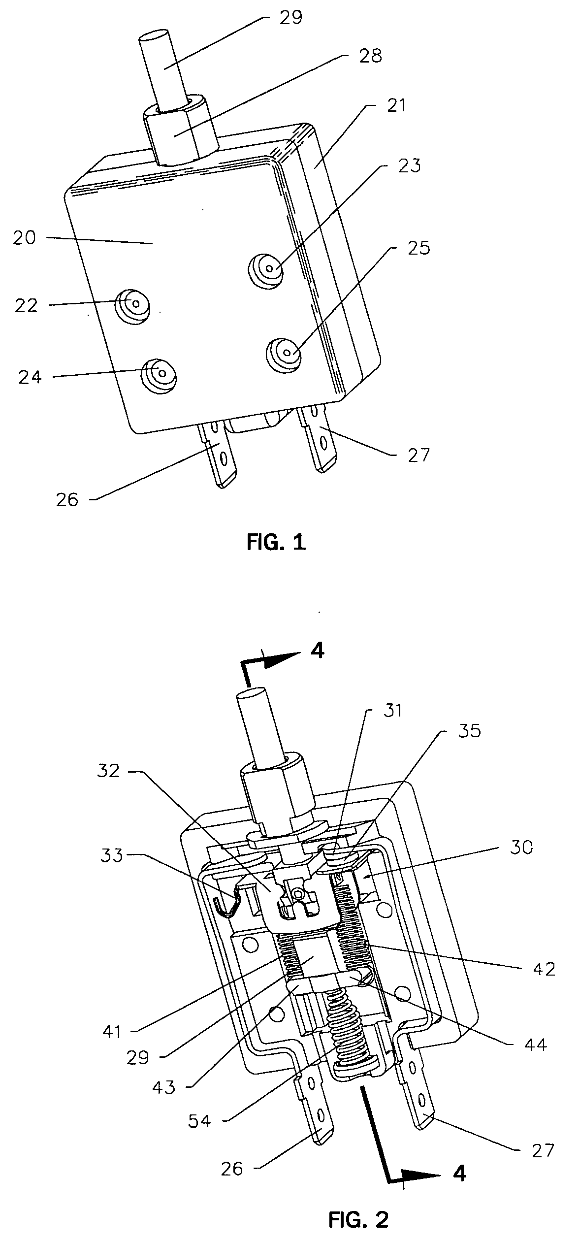
[0021] In FIG. 1, the circuit breaker is shown composed of two similar case halves 20 and 21 made from molded insulating material. Rivets 22, 23, 24 and 25 permanently hold the assembled breaker together. The conductors 26 and 27 used to connect the breaker to an electric circuit extend outwardly from the bottom of the case halves. Extending outwardly from the top of the case halves is a mounting sleeve 28 which provides a means to restrain the breaker for use. Extending outwardly from the top of the mounting sleeve 28 is an actuator plunger 29, which is used to reset a tripped breaker.

[0022] The casing sections combine to form an enclosed separable contact chambe...


PUM


Abstract

The invention relates to a re-settable, single-phase, thermo/electric circuit breaker utilizing a U-shape bimetallic element of substantial resistance properties in the circuit, so that when a predetermined overload current occurs the bimetallic element self heats and moves to trip a mechanism that opens the breaker circuit. The invention replaces the double-contact break configuration normally associated with a breaker of this type, with a single contact break configuration designed to produce a sliding action between contacts during the normal reset operation, providing a more reliable continuity at the moveable and stationary contact interface that is also less expensive to produce.

Description

BACKGROUND OF THE INVENTION [0001] 1. Field of Use [0002] The invention comprises a resettable thermo / electric circuit breaker of a type utilizing a single-contact break supported by a U-shaped bimetallic thermal sensing element. [0003] 2. Description of Related Art [0004] Circuit breakers utilizing a double-contact break supported by a U-shaped bimetallic thermal sensing unit are widely used in electric circuits to prevent current overload. Examples of this type of prior art circuit breaker, all of which are assigned to the assignee of this invention, include the Series 02 circuit breaker depicted in FIG. 9 and inventions disclosed in U.S. Pat. Nos. 2,513,564; 2,514,545; and 2,689,895. Because of the relatively high contact resistance associated with the two pairs of contacts utilized in these designs, they are susceptible to intermittent loss of electrical continuity for applications involving low open circuit voltage. Each time the circuit breaker contacts are opened and reclosed...

Claims


Application Information

Patent Timeline
IPC IPC(8): H01H71/16
CPCH01H71/16H01H71/74H01H73/30
Inventor ALLISON, JAMESPOLLOCK, WILLIAM
Owner MP HOLLYWOOD
Why Eureka
Try Eureka