System and method for microwave imaging using programmable transmission array

a technology of programmable transmission array and microwave imaging, which is applied in the direction of geological detection using milimeter waves, instruments, and antennas, etc., can solve the problems of inability to detect non-metallic objects, inability to reliably and invasively, and inability to physically inspect security personnel. tedious, unreliable and invasive problems

Active Publication Date: 2006-05-25
AGILENT TECH INC
View PDF34 Cites 27 Cited by
  • Summary
  • Abstract
  • Description
  • Claims
  • Application Information

AI Technical Summary

Problems solved by technology

However, physical inspection by security personnel is tedious, unreliable and invasive.
In addition, metal detectors are prone to false alarms, and are not capable of detecting non-metallic objects, such as plastic or liquid explosives, plastic or ceramic handguns or knives and drugs.
Furthermore, X-ray systems pose a health risk, particularly to those people who are repeatedly exposed to X-ray radiation, such as airport personnel, and X-ray systems also are not able detect certain materials / geometries, such as ceramic knives.
However, such scanning systems typically require mechanically moving parts and / or intensive post-processing reconstruction of the image, both of which increase the cost and complexity of the microwave imaging system.
However, microwave imaging systems that use lenses to focus the microwave energy typically have a limited field of view and small aperture size.
In addition, the cost of the lens system may be prohibitively large in many applications.

Method used


Image

  • System and method for microwave imaging using programmable transmission array
  • System and method for microwave imaging using programmable transmission array
  • System and method for microwave imaging using programmable transmission array

Examples


Embodiment Construction

[0023] As used herein, the terms microwave radiation and microwave illumination each refer to the band of electromagnetic radiation having wavelengths between 0.3 mm and 30 cm, corresponding to frequencies of about 1 GHz to about 1,000 GHz. Thus, the terms microwave radiation and microwave illumination each include traditional microwave radiation, as well as what is commonly known as millimeter-wave radiation.

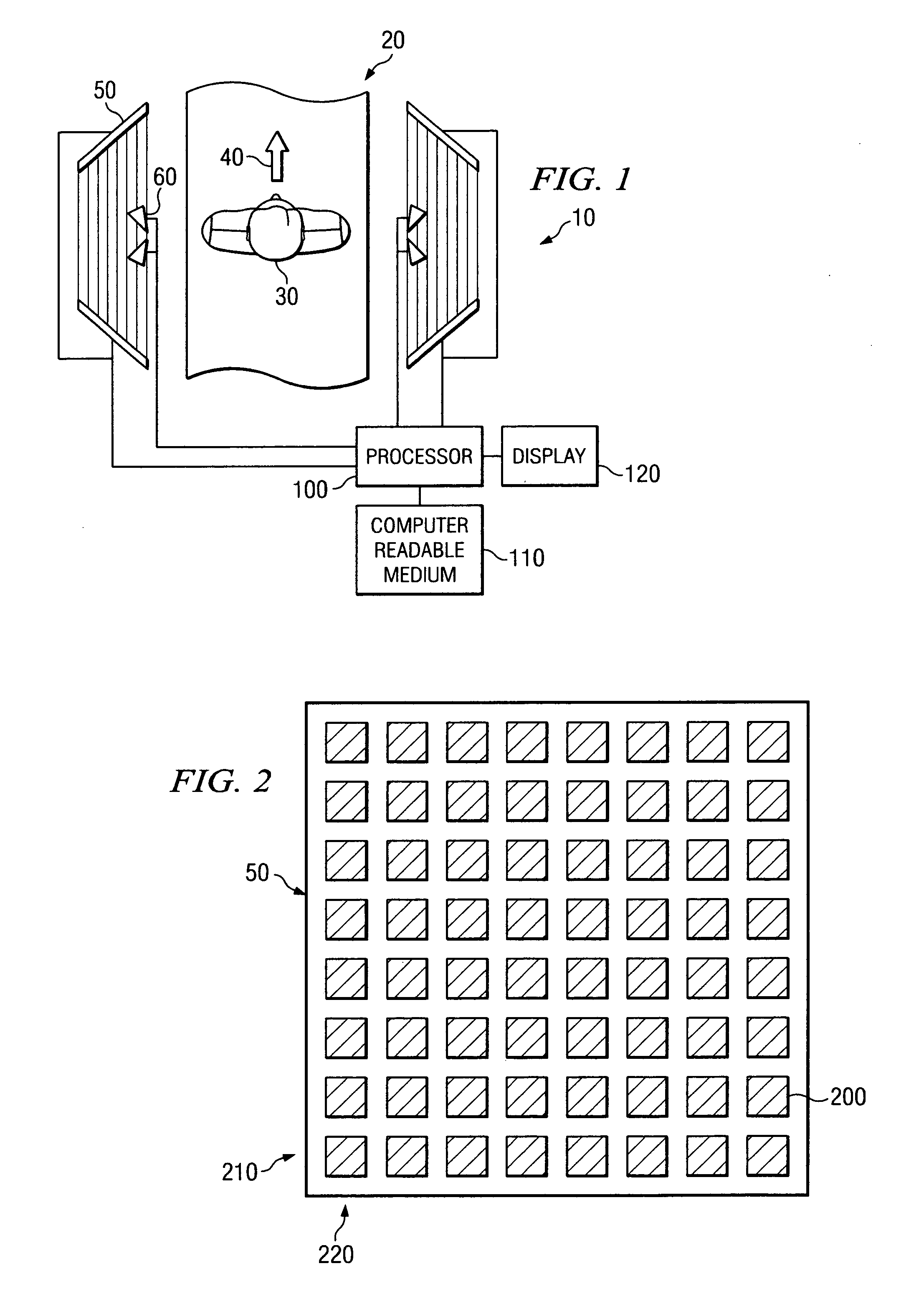
[0024]FIG. 1 is a schematic diagram of a simplified exemplary microwave security inspection system 10, in accordance with embodiments of the present invention. The microwave security inspection system 10 includes a portal 20 through which a human subject 30 is capable of walking. The portal 20 does not include any moving parts, and therefore, the human subject 30 is able to walk at a normal pace in a single direction 40 through the portal 20. By enabling the human subject 30 to walk through the portal 20, the throughput of the system 10 is maximized, while also minimizing the ...


PUM


Abstract

A microwave imaging system uses microwave radiation provided by a microwave source to image targets. The system includes an array of antenna elements that are capable of being programmed with a respective transmission coefficient to direct the microwave illumination from the microwave source toward a position on the target. The antenna elements are further capable of being programmed with a respective additional transmission coefficient to receive reflected microwave illumination reflected from the position on the target and direct the reflected microwave illumination towards a microwave receiver. A processor is operable to measure an intensity of the reflected microwave illumination to determine a value of a pixel within an image of the target. Multiple beams can be directed towards the target to obtain corresponding pixel values for use by the processor in constructing the image.

Description

BENEFIT CLAIM UNDER 35 U.S.C. § 120 [0001] This application is a continuation-in-part of prior U.S. Non-provisional Application for patent Ser. No. 10 / 996,764 filed on Nov. 24, 2004. CROSS-REFERENCE TO RELATED APPLICATIONS [0002] This application is related by subject matter to U.S. Non-provisional Application for patent Ser. No. ______ (Attorney Docket No. 10040151), entitled “A Device for Reflecting Electromagnetic Radiation” and U.S. Non-provisional Application for patent Ser. No. ______ (Attorney Docket No. 10040580), entitled “Broadband Binary Phased Antenna,” both of which were filed on Nov. 24, 2004.BACKGROUND OF THE INVENTION [0003] In response to an increasing threat of terrorism, inspection of persons and other items for weapons and other types of contraband is becoming essential at security checkpoints, such as those found at airports, concerts, sporting events, courtrooms, federal buildings, schools and other types of public and private facilities potentially at risk fro...

Claims


Application Information

Patent Timeline
Patent Type & Authority Applications(United States)
IPC IPC(8): G01S13/89
CPCG01S13/04G01S13/89G01V8/005H01Q3/26H01Q21/065G01V3/12
Inventor BAHARAV, IZHAKTABER, ROBERT C.LEE, GREGORY S.KOFOL, JOHN STEPHEN
Owner AGILENT TECH INC
Why Eureka
Try Eureka