Plasma display apparatus and driving method thereof

a technology of plasma display and driving method, which is applied in the direction of instruments, static indicating devices, etc., can solve the problems of overheating and destroying the capacitor cs, increasing the energy loss of the plasma display apparatus, and increasing the temperature of the switching device, so as to prevent an excessive voltage

Inactive Publication Date: 2006-05-25
LG ELECTRONICS INC
View PDF7 Cites 9 Cited by
  • Summary
  • Abstract
  • Description
  • Claims
  • Application Information

AI Technical Summary

Benefits of technology

[0022] Accordingly, the present invention has been made in view of the above problems occurring in the prior art, and it is an object of the present invention to provide a plas

Problems solved by technology

As a result, an energy loss of the plasma display apparatus is increased and the temperature of a switching device is raised.
At this time, a voltage continues to be applied to the capacitor Cs through the second switch S2, and thus an excessive energy is accumulated in the capacitor Cs, thereby overheati

Method used


Image

  • Plasma display apparatus and driving method thereof
  • Plasma display apparatus and driving method thereof
  • Plasma display apparatus and driving method thereof

Examples


Embodiment Construction

[0039] The present invention will now be described in detail in connection with preferred embodiments with reference to the accompanying drawings.

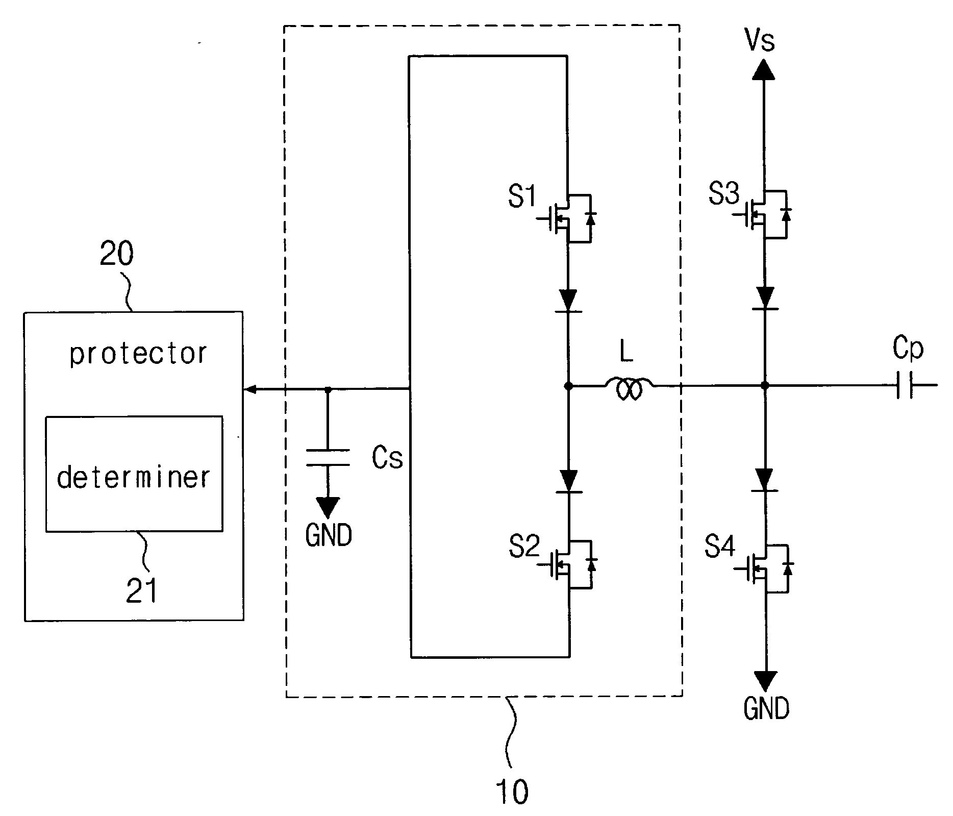
[0040] According to an aspect of the present invention, a plasma display apparatus comprising: a plasma display panel in which a plurality of electrodes are formed; an energy storage unit for storing energy applied to the electrodes; and a protector for maintaining a voltage level of the energy stored in the energy storage unit at a predetermined voltage range.

[0041] The predetermined voltage range is 95% to 105% of a predetermined reference voltage level.

[0042] The reference voltage level is substantially half a sustain voltage. The reference voltage level is substantially half an address voltage.

[0043] The predetermined voltage range is 20% to 80% of a storage capacitance of the energy storage unit.

[0044] The protector comprises a determiner for determining whether the voltage level of the energy is outside of the predetermined volt...


PUM


Abstract

A plasma display apparatus and a driving method thereof are disclosed. The plasma display apparatus comprises a plasma display panel in which a plurality of electrodes are formed, an energy storage unit for storing energy applied to the electrodes, and a protector for maintaining a voltage level of the energy stored in the energy storage unit at a predetermined voltage range.

Description

CROSS-REFERENCES TO RELATED APPLICATIONS [0001] This Nonprovisional application claims priority under 35 U.S.C. § 119(a) on Patent Application Nos. 10-2004-0096977 and 10-2005-0042758 filed in Korea on Nov. 24, 2004 and May 21, 2005 the entire contents of which are hereby incorporated by reference. BACKGROUND OF THE INVENTION [0002] 1. Field of the Invention [0003] The present invention relates to a plasma display apparatus and a driving method thereof [0004] 2. Background of the Related Art [0005] Generally, a plasma display apparatus comprises a plasma display panel in which barrier ribs formed between a front panel and a rear panel constitute a single unit cell. Each cell is filled with a main discharge gas, such as neon (Ne), helium (He) or a mixed gas (Ne+He) of Ne and He, and an inert gas comprising a small amount of xenon Xe. When those gases are discharged by a high frequency voltage, the inert gas generates vacuum ultraviolet rays and radiates a phosphor material formed bet...

Claims


Application Information

Patent Timeline
IPC IPC(8): G09G3/28G09G3/288G09G3/293G09G3/296
CPCG09G3/293G09G3/2965
Inventor CHO, JANGHWANPARK, DONGHYUKKWON, CHANGYOUNGCHOI, DONG KWONAN, YANG KIKIM, JINYOUNGJUNG, YUNKWON
Owner LG ELECTRONICS INC
Why Eureka
Try Eureka