Optical information recording medium

Inactive Publication Date: 2006-05-25
OPTWARE
View PDF7 Cites 29 Cited by
  • Summary
  • Abstract
  • Description
  • Claims
  • Application Information

AI Technical Summary

Benefits of technology

[0014] A gap layer for smoothing the substrate surface is provided between the filter layer and the reflective surface. This g

Problems solved by technology

This is problematic in that the reproduction image cannot be correctly detected by CMOS sensor or CCD and because it is extremely difficult to separate this noise.
Because servo light is red light, it can be separated from the green light of information light and recording/reproduction reference lights,

Method used


Image

  • Optical information recording medium
  • Optical information recording medium
  • Optical information recording medium

Examples


first embodiment

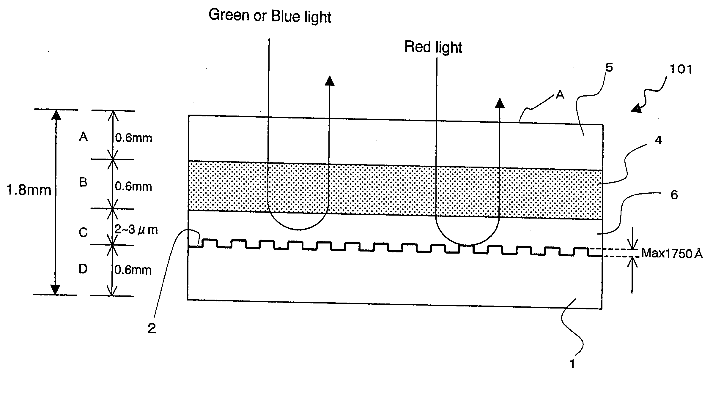
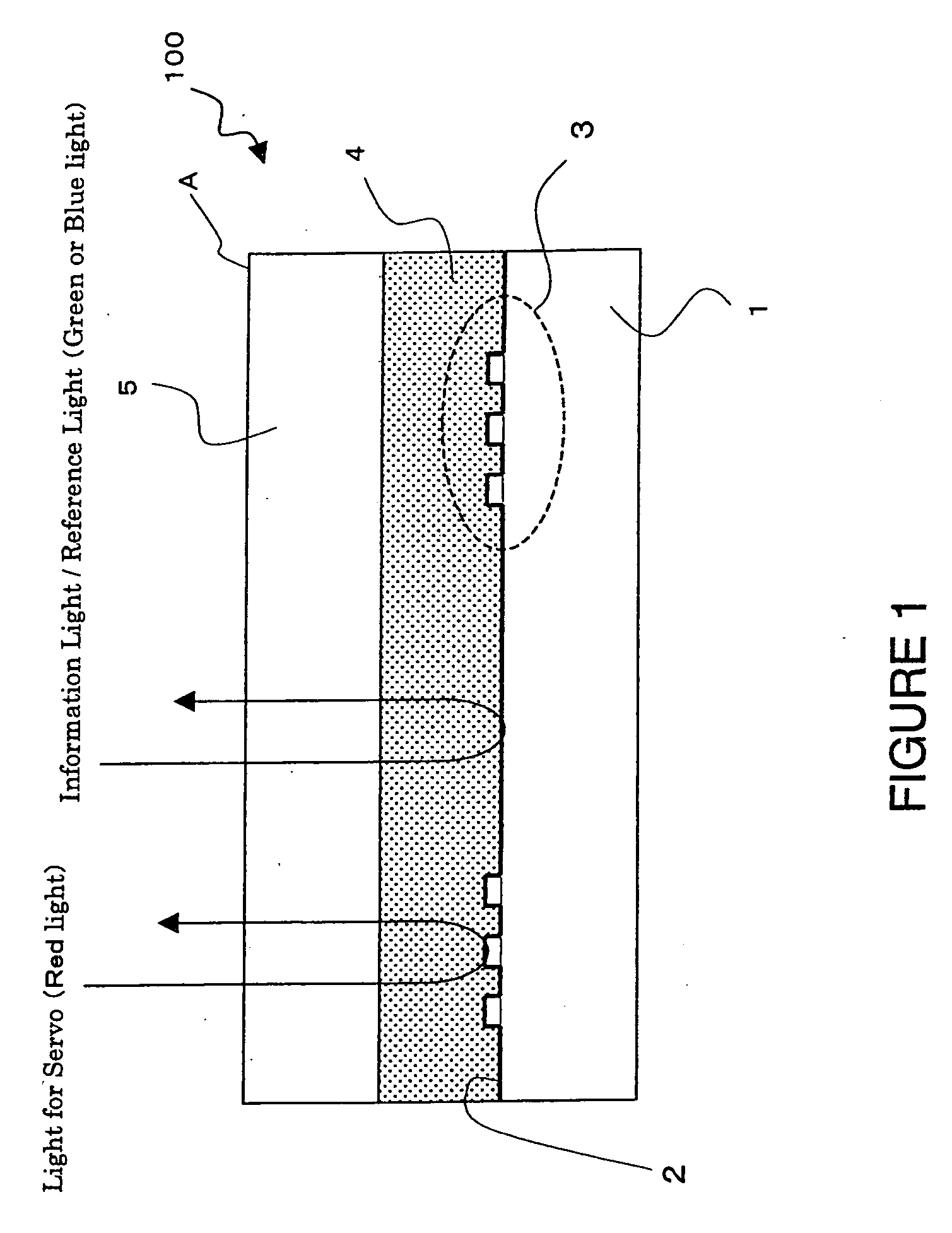
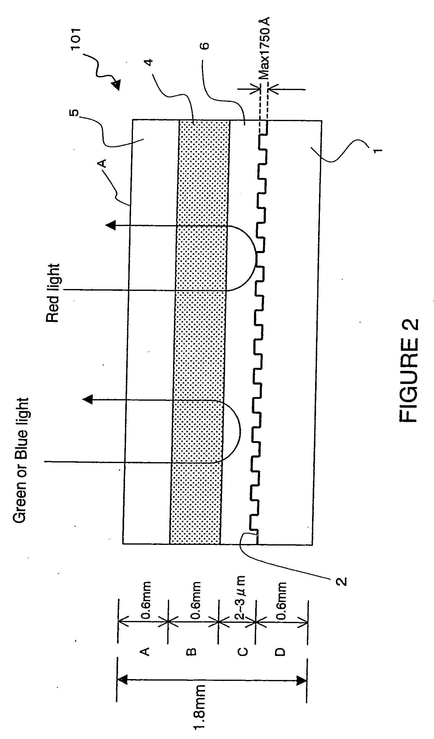
[0021]FIG. 2 is a diagram showing the structure of an optical information recording medium according to a first embodiment. In optical information recording medium 101 according to the first embodiment, servo pit is formed on a polycarbonate or glass substrate 1 and is coated with aluminum, gold, platinum, etc. to provide a reflective layer 2. Although, unlike FIG. 1, servo pit is formed on the entire surface of the substrate in FIG. 2, it can also be formed cyclically as in FIG. 1. In addition, the height of this servo pit is 1750 Å maximum and is sufficiently small compared to the thickness of the substrate and other layers.

[0022] In addition, a red-colored light transmitting filter layer 6 is provided on substrate 1 with reflective layer 2 and optical information recording medium 100 is constructed by sandwiching hologram recording material which is hologram recording layer 4 between this layer 6 and upper substrate 5 (polycarbonate, glass, etc).

[0023] In FIG. 1, the red-colore...

second embodiment

[0027]FIG. 3 is a diagram showing the structure of an optical information recording medium according to a second embodiment. In optical information recording medium 102 according to the second embodiment, servo pit is formed on a polycarbonate or glass substrate 1 and is coated with aluminum, gold, platinum, etc. to provide a reflective layer 2. With regards to the height of this servo pit being a maximum of 1750 Å, it is the same as in the first embodiment.

[0028] The structural differences between the second embodiment and the first embodiment is that, in optical information recording medium 102 according to the second embodiment, there is a gap layer 8, a dichroic mirror layer 9 is provided in place of filter layer 6 of optical information recording medium 101, and furthermore, a quarter-wavelength board layer 7 is provided between dichroic mirror layer 9 and hologram recording layer 4.

[0029] Gap layer 8 is formed on reflective layer 2 of substrate 1 by applying spin coat or the...

third embodiment

[0035]FIG. 4 is a diagram showing the structure of an optical information recording medium according to a third embodiment. In optical information recording medium 103 according to the third embodiment, a cholesteric liquid crystal layer 10 is provided in place of dichroic mirror layer 9 in the second embodiment. Other structures are the same as the second embodiment.

[0036] The thickness of this cholesteric liquid crystal layer 10 is also 1 to 2 μm, and as with the other embodiments, the thickness of the entire optical information recording medium is approximately 1.8 mm.

[0037] Cholesteric liquid crystal layer 10 is formed by applying, for example, cholesteric liquid crystal CM-33 (Chisso Corporation product), which is a chiral dopant, after forming gap layer (smooth layer) 8, and spin-coating. Cholesteric liquid crystal has characteristics wherein light is reflected when circularly-polarized light of a predetermined direction is incident, and light is transmitted when other light...


PUM


Abstract

An optical information recording medium having a structure in which irregular reflection of information light and recording/reproducing light from the reflective layer of an optical information record medium is prevented, thereby reducing the noise appearing on the reproduced image. The optical information recording medium for recording information by holography comprises a transparent substrate, a recording layer where information is recorded by an interference pattern, and a filter layer formed between the transparent substrate and the recording layer and adapted to transmit a light of a first wavelength and reflect a light of a second wavelength. The filter layer of the thus structured optical information recording medium transmits a light of the first wavelength (for example, red light) and reflects a light of the second wavelength (for example, green light). As a result, two lights of different wavelengths can be separated and used for different purposes without being influenced by each other.

Description

BACKGROUND OF THE INVENTION [0001] 1. Field of the Invention [0002] The present invention relates to an optical information recording medium wherein information is recorded utilizing holography. In particular, the present invention relates to a structure of an optical information recording medium wherein the generation of diffusive light from a reflective surface which causes various adverse effects is prevented when the reflective surface provided on the substrate of an optical information recording medium is irradiated with information light and recording / reproduction reference light. [0003] 2. Description of the Related Art [0004] Holographic recording for recording information to a recording medium using holography is generally performed by superimposing light holding image information and reference light within the recording medium and writing the interference pattern formed at this time to the recording medium. When reproducing the recorded information, the image information i...

Claims


Application Information

Patent Timeline
IPC IPC(8): G11B7/24G02B5/28G02B5/30G02F1/13G03H1/02G03H1/18G11B7/007
CPCG11B7/0938G11B7/2403G11B7/24044G11B7/2405
Inventor HORIMAI, HIDEYOSHIAOKI, YOSHIOTOGO, ATSUSHI
Owner OPTWARE
Why Eureka
Try Eureka