
Modeless wavelength-agile laser

a wavelength-agile, laser technology, applied in the field of lasers, can solve the problem of limited frequency change speed, and achieve the effect of reducing speckles and high cavity length change ra

Active Publication Date: 2006-05-25
WISCONSIN ALUMNI RES FOUND
View PDF12 Cites 47 Cited by
  • Summary
  • Abstract
  • Description
  • Claims
  • Application Information

AI Technical Summary

Benefits of technology

The present invention provides a laser that can change its cavity length quickly to prevent the formation of laser modes. This results in a spectrally narrow, swept-wavelength light source that is resistant to mode hopping and reduced speckle. The laser has a high rate of cavity length change, which is achieved by a pivoting mirror design. The speed at which the cavity length must be changed is such that, in the time it takes light to cycle through the cavity, the length is changed by an appreciable fraction of the wavelength. The cavity length may change by no less than ⅛ of a wavelength of emitted photons during a period defined by the round trip transit time of the photons along the cavity length and preferably no less than 1% of that wavelength. The means for varying the cavity length may include a mirror pivoting about an axis to direct photons to a retro reflector having a surface with different portions of varying distance from the mirror. The invention combines the functions of frequency selectivity and retro-reflector for cavity length change in a single optical element. The optical system may separately provide a means for varying the wavelength of the photons and for varying the cavity length independently of the wavelength of the photons to substantially prevent formation of resonant modes.

Problems solved by technology

This speed of frequency change can be limited by mechanical constraints incident to coordinated movement of the optical grating and change in cavity length.

Method used


Image

  • Modeless wavelength-agile laser
  • Modeless wavelength-agile laser

Examples


Embodiment Construction

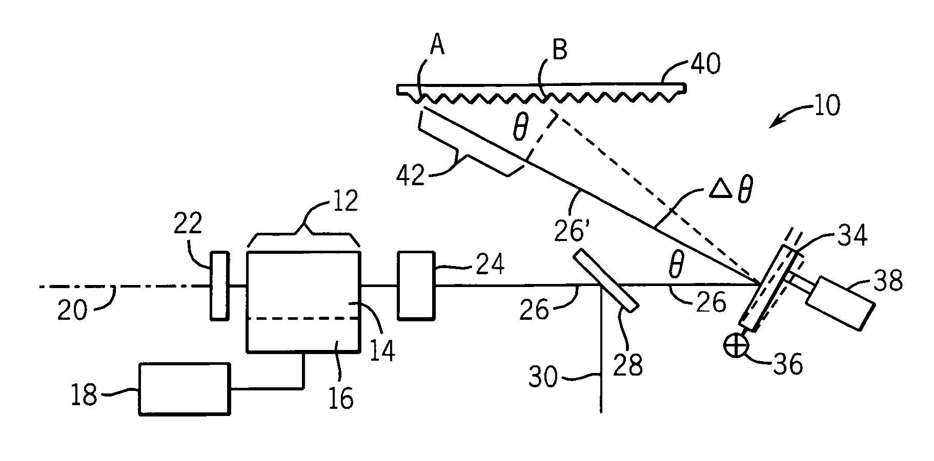
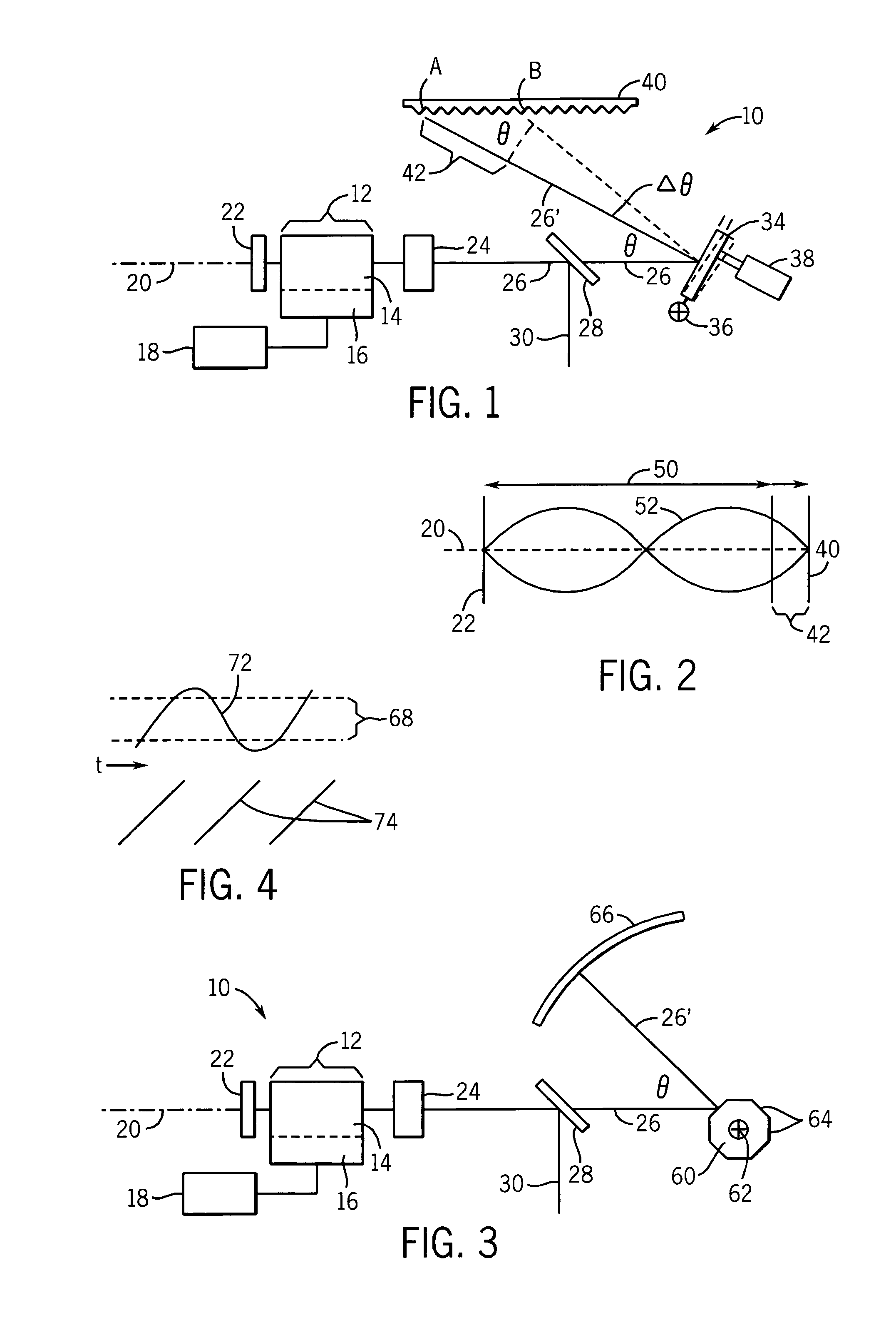
[0028] Referring now to FIG. 1, a frequency agile modeless laser 10 includes a laser source 12 providing a laser medium 14 such as supports the stimulated emission of photons, and an energy pump 16 and power supply 18 exciting the of the laser medium 14 into a stimulated state.

[0029] The laser medium 14 is preferably a solid-state material forming part of a solid-state laser diode, for example, in which case the pump 16 is an electrode of the diode. More generally, the laser medium 14 may be any suitable laser material and the pump 16 may be an optical or electrical pump for stimulating the electrons of the laser medium 14 as will be understood in the art.

[0030] The laser medium 14 may emit photons along an optical axis 20 extending through a front and rear surface of the laser medium 14. At the rear surface of the laser medium, the optical axis 20 is intercepted by a mirror 22 which reflects emitted photons back into the laser medium 14. The photons emitted from the front surface...


PUM


Abstract

An external cavity laser may be swept rapidly in frequency and cavity length to prevent formation of modes providing improved spectral response and light characteristics.

Description

CROSS-REFERENCE TO RELATED APPLICATIONS STATEMENT REGARDING FEDERALLY SPONSORED RESEARCH OR DEVELOPMENT BACKGROUND OF THE INVENTION [0001] The present invention relates to lasers and more particularly to a laser providing a rapidly sweeping light frequency without laser modes. [0002] Spectroscopic studies evaluate the “spectrographic” response of a material to different frequencies of light. The spectrographic response may be light absorption, reflectivity, scattering, fluorescence or other features. [0003] Spectrographic studies may be used to investigate gases, liquids, aerosols, solids, particulates, and the like, as their physical properties change in response to temperature, pressure, velocity, composition, size, stress and strain. Similar techniques may be used to monitor sensors incorporating materials whose spectrographic responses change as a function of a physical parameter to be measured. [0004] Spectroscopic studies may use a “wavelength-agile” light source providing a s...

Claims


Application Information

Patent Timeline
Patent Type & Authority Applications(United States)
IPC IPC(8): H01S3/098
CPCH01S3/08059H01S5/141H01S5/143
Inventor SANDERS, SCOTT T.
Owner WISCONSIN ALUMNI RES FOUND
Learn More