Air compressor

a compressor and air technology, applied in the direction of machines/engines, positive displacement liquid engines, pump control, etc., can solve the problems of increasing the load on the bearing parts of ball bearings and needle bearings used in motors, increasing the pressure inside the cylinder increasing the driving torque of the piston for creating compressed air, so as to prolong the life of the air compressor and reduce the wear of the inner wall of the cylinder of the driver portion and the piston ring. , the effect o

Inactive Publication Date: 2006-05-25
KOKI HLDG CO LTD
View PDF1 Cites 29 Cited by
  • Summary
  • Abstract
  • Description
  • Claims
  • Application Information

AI Technical Summary

Benefits of technology

[0012] However, with the prior art small-sized air compressor, if the motor stop pressure Poff is increased, the pressure inside the cylinder for creating compressed air increases. Therefore, the frictional force between the inner wall of the cylinder and the piston ring increases. Furthermore, the driving torque of the piston for creating compressed air increases. This increases the loads that bearings such as ball bearings and needle bearings used in the motor undergo.
[0013] Therefore, in the prior art technique, if one attempts to improve the continuous operable time of a pneumatic tool consuming a large amount of compressed air by increasing the amount of usable air, which is enabled by increasing the motor stop pressure Poff of the pressure inside the tank, there arises the problem that the life of the air compressor shortens.
[0014] Accordingly, it is an object of the present invention to provide a technique for controlling a motor that drives a compressed air creation portion which deteriorates neither the life nor the performance of an air compressor.
[0015] It is another object of the invention to provide an air compressor which is especially of the portable type and which permits elongation of the continuous operable time of a pneumatic tool connected with the air compressor by increasing the motor stop pressure (Poff) of compressed air stored in the tank.
[0022] According to the above-described features of the present invention, in a case where the rate of decrease of pressure of the compressed air inside the tank portion is greater than the given value, the motor is immediately started. When the pressure inside the tank portion has increased to the given motor stop pressure value (Poff), the motor is stopped. On the other hand, in a case where the rate of decrease of pressure is below the given value, the motor is started when the pressure of the compressed air inside the tank portion has decreased to a given motor restart pressure value (Pon). When the pressure of the compressed air inside the tank portion has increased to a given pressure value that is lower than the motor stop pressure value (Poff), the motor is controlled to come to a stop. Accordingly, when the amount of consumption of the compressed air is small, the motor driving is stopped under high-pressure conditions by lowering the motor stop pressure. As a result, the wear of the inner wall of the cylinder of the driver portion and of the piston ring and load on the bearing portions can be reduced. The life of the air compressor can be prolonged.
[0023] According to the feature of the invention of the above-described item (3), a state in which the amount of air consumption is relatively large can be detected at early times by the rate of decrease of pressure (ΔP1 / ΔT1) within a relatively short time. On the other hand, a relatively large pressure decrease (ΔP2) that cannot be detected within a short time (ΔT1) such as in a case where a pneumatic tool is used at intervals can be detected by means of the rate of decrease of the pressure (ΔP2 / ΔT2) over a relatively long time (ΔT2). Consequently, the pressure can be controlled efficiently.

Problems solved by technology

However, with the prior art small-sized air compressor, if the motor stop pressure Poff is increased, the pressure inside the cylinder for creating compressed air increases.
Furthermore, the driving torque of the piston for creating compressed air increases.
This increases the loads that bearings such as ball bearings and needle bearings used in the motor undergo.
Therefore, in the prior art technique, if one attempts to improve the continuous operable time of a pneumatic tool consuming a large amount of compressed air by increasing the amount of usable air, which is enabled by increasing the motor stop pressure Poff of the pressure inside the tank, there arises the problem that the life of the air compressor shortens.

Method used


Image

  • Air compressor
  • Air compressor
  • Air compressor

Examples


Embodiment Construction

[0029] Embodiments of the present invention are hereinafter described in detail with reference to FIGS. 1-4. In all the figures illustrating the embodiments, members having the same function are indicated by the same numeral and their repeated description is not provided.

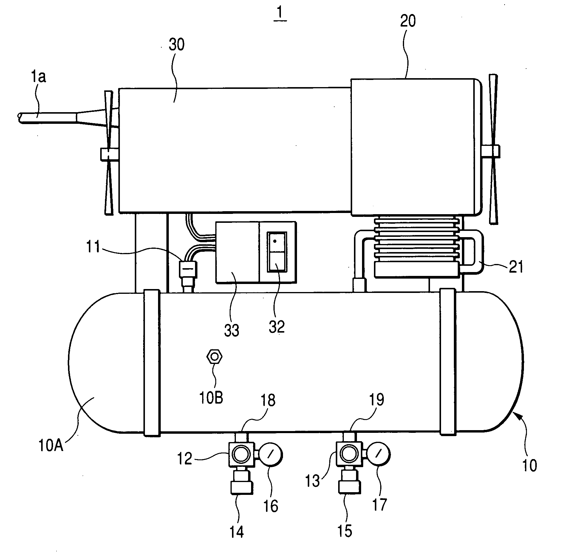
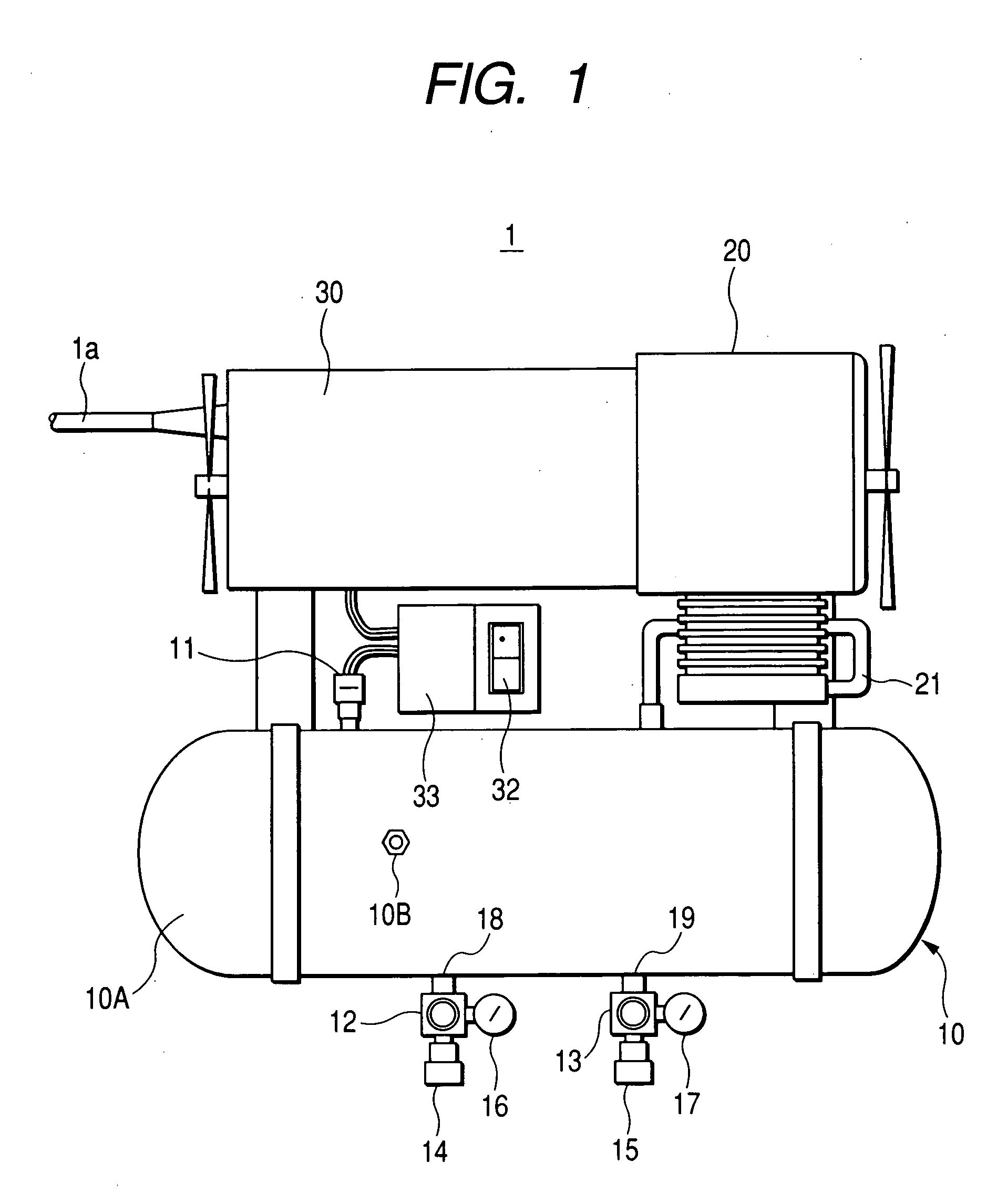
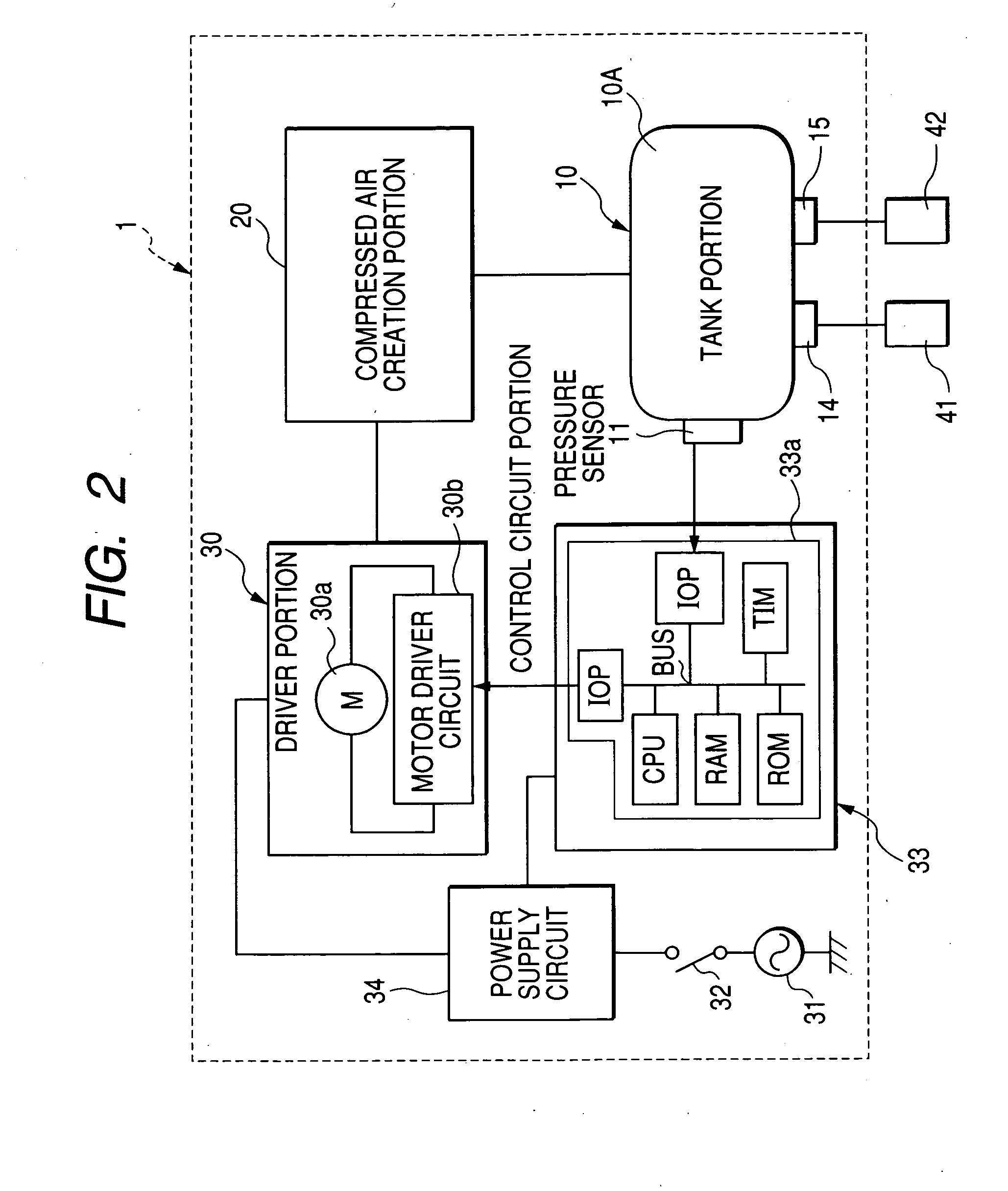
[0030]FIG. 1 is a front elevation showing the outer appearance of an air compressor of the present invention. FIG. 2 is a block diagram showing the electrical and mechanical systems according to the air compressor of the invention.

[0031] As shown in FIG. 1, an air compressor 1 associated with the present invention has a tank portion 10 for storing compressed air, a pressure sensor 11 for detecting the pressure of compressed air inside the tank portion 10, a compressed air creation portion 20 for creating the compressed air, a driver portion 30 having a motor 30a (see FIG. 2) for driving the compressed air creation portion 20, and a control circuit portion 33 for controlling start and stop (turning on and off) of t...


PUM


Abstract

A control circuit portion in an air compressor finds the rate of decrease of pressure inside a tank portion when a motor is at rest relative to the time based on a detection signal from a pressure sensor. Where the rate of decrease of pressure is greater than a given value, the motor is started without waiting for the pressure inside the tank to decrease to a motor restart pressure value, the pressure inside the tank portion rises to a given motor stop pressure value and the motor is then controlled to come to a stop. Where the rate of decrease of pressure is less than the given value, the motor is started when the pressure inside the tank has decreased to the motor restart pressure value. After the start of the motor, the motor is controlled such that it comes to a stop when the pressure inside the tank portion increases to a given value lower than the motor stop pressure value.

Description

BACKGROUND OF THE INVENTION [0001] 1. Field of the Invention [0002] The present invention relates to an air compressor for creating compressed air for driving a pneumatic tool such as a nailing machine. [0003] 2. Description of the Related Art [0004] Generally, an air compressor for driving a pneumatic tool is designed to convert rotary motion of a motor into reciprocatory motion of a piston inside a cylinder via a crankshaft such that air sucked in from the suction valve of the cylinder is compressed by the reciprocatory motion of the piston. The air compressed within the cylinder is discharged into an air tank through a pipe from an exhaust valve and stored in the tank. A pneumatic tool such as a nailing machine operates by making use of the compressed air stored in the tank. [0005] Such a conventional air compressor may be, in a rare case, of the stationary type having a large-sized air tank having a large capacity of creating compressed air. However, generally, air compressors a...

Claims


Application Information

Patent Timeline
Patent Type & Authority Applications(United States)
IPC IPC(8): F04B49/00
CPCF04B49/08
Inventor IIMURA, YOSHIOORIKASA, HIROAKI
Owner KOKI HLDG CO LTD
Why Eureka
Try Eureka