System for adjusting resonance frequencies in a linear compressor

a linear compressor and resonance frequency technology, applied in the direction of positive displacement liquid engine, piston pump, pump parameter, etc., can solve the problems of loss of motor efficiency, unbalance between mechanical resonance frequency and electrical supply frequency of the power system and achieve adequate volumetric yield, high cost, and high energy loss

Inactive Publication Date: 2006-05-25
EMPRESA BRASILEIRA DE COMPRESSORES SA (EMBRACO)
View PDF9 Cites 83 Cited by
  • Summary
  • Abstract
  • Description
  • Claims
  • Application Information

AI Technical Summary

Benefits of technology

[0017] a system for adjusting the resonance frequencies in a linear compressor, which controls and conducts the mechanical resonance frequency of the compressor, at least in determined operational conditions, to values that are substantially close to the electrical supply frequency of the compressor, without presenting the high costs and high energy losses of the electronic control systems.
[0018] It is a further object of the invention to provide a system such as mentioned above, which maintains the dead volume of the compressor at a minimum value during the operation thereof, maintaining an adequate volumetric yield, with minimum energy loss.

Problems solved by technology

In determined situations, the loss of balance between the electrical and mechanical frequencies in the compressor results, for the latter, in a higher need of energy to maintain the pumping of gas.
In a situation in which the refrigeration appliance is conducted from a turn-off condition to a turn-on condition, the refrigeration system of this appliance is submitted to high pressure peaks, with maximum pumping capacity, which increases the mechanical resonance frequency of the compressor, causing unbalance between said mechanical resonance frequency and the electrical supply frequency of the power system.
Since the motor yield is a function of its effort to operate, there is loss of motor efficiency whenever the mechanical resonance frequency is not equalized with the electrical supply frequency of the power system.
However, this solution is expensive and presents energy loss.

Method used


Image

  • System for adjusting resonance frequencies in a linear compressor
  • System for adjusting resonance frequencies in a linear compressor
  • System for adjusting resonance frequencies in a linear compressor

Examples


Embodiment Construction

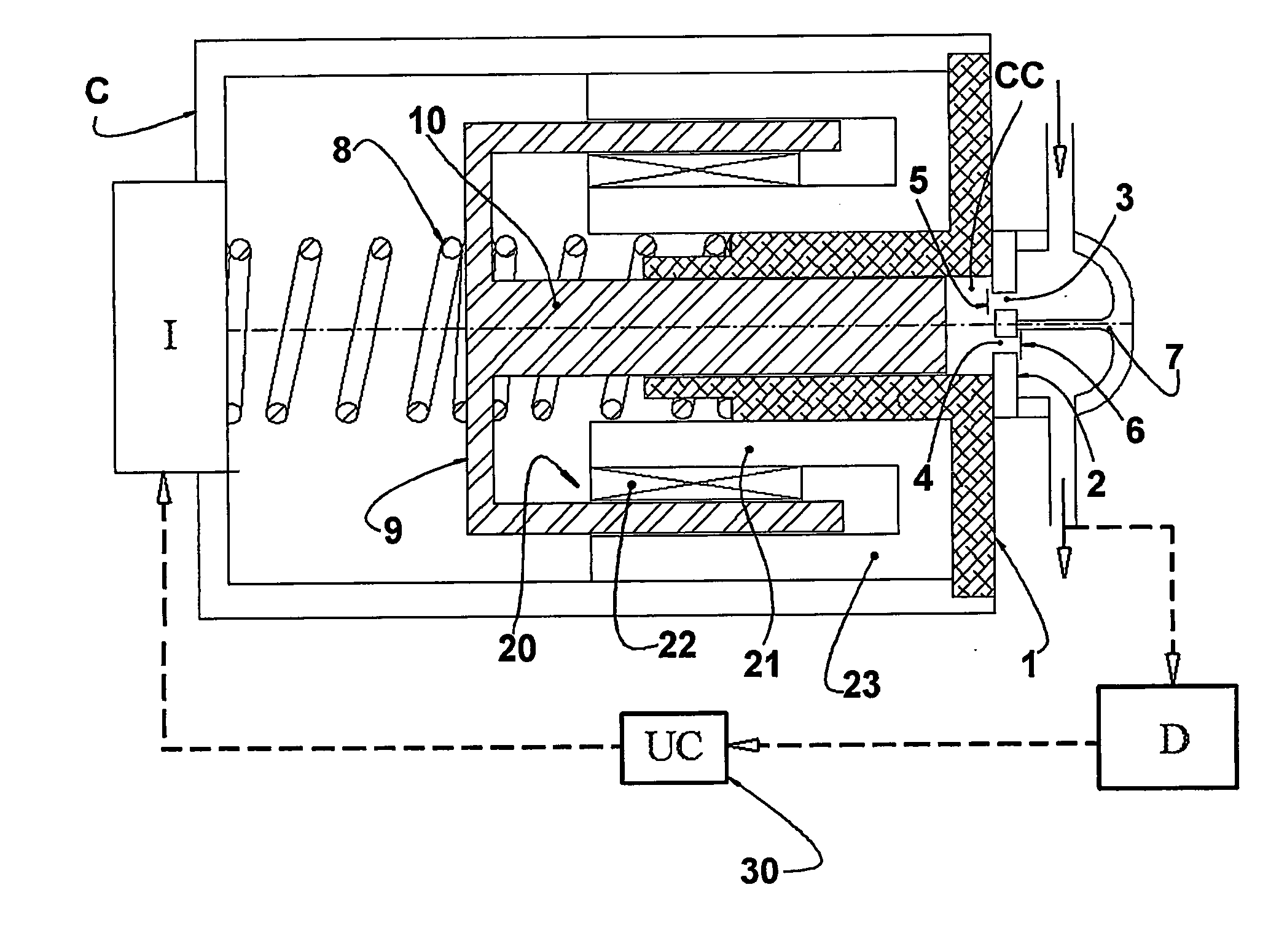
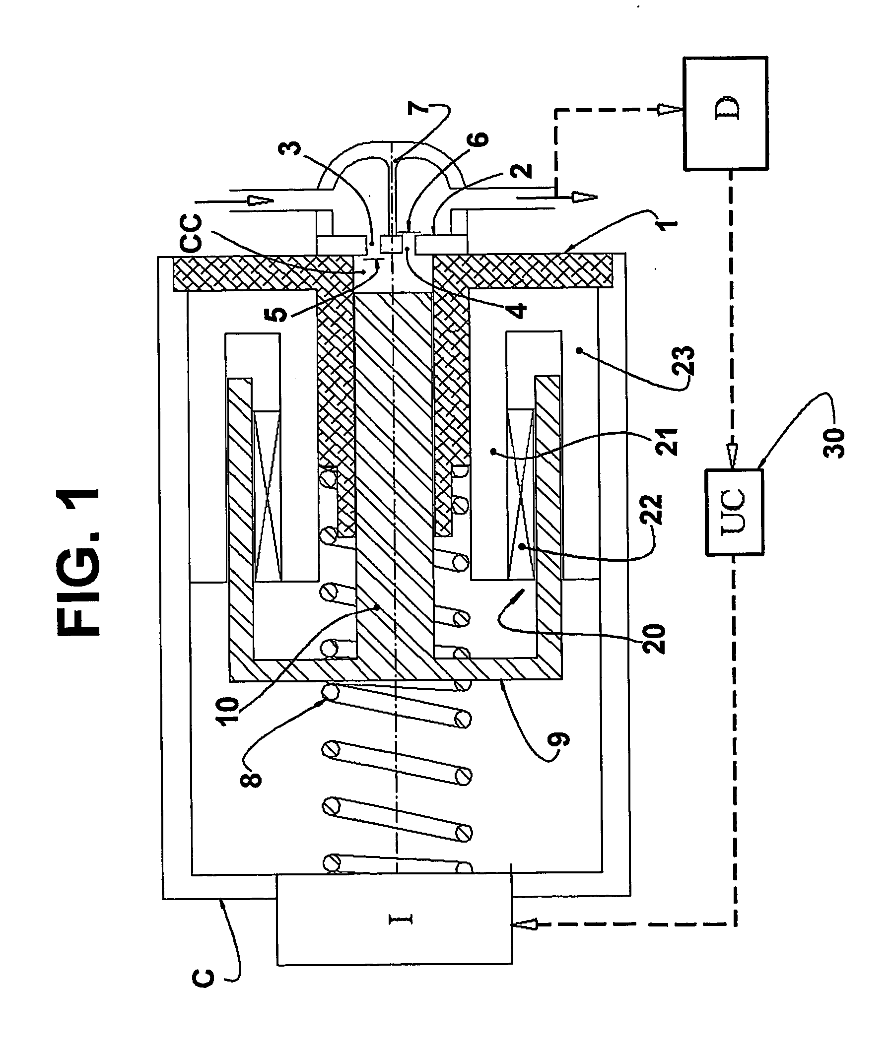
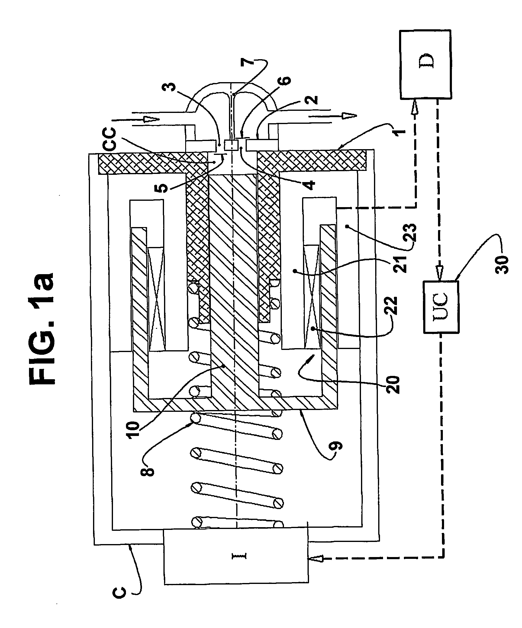
[0031] The present invention will be described in relation to a reciprocating compressor driven by a linear motor of the type used in refrigeration systems and comprising, within a hermetic shell (not illustrated), a motor-compressor assembly including a cylinder 1, which is closed, at one of the ends thereof, by a valve plate 2, and inside which is provided a piston 10 reciprocating in consecutive suction and compression strokes.

[0032] In conventional constructions, an internal lower portion of the shell defines a reservoir for the lubricant oil of the compressor.

[0033] In the valve plate 2 there are defined a suction orifice 3 and a discharge orifice 4 of the compressor, which are respectively and selectively closed by a suction valve 5 and by a discharge valve 6, in order to allow the selective fluid communication between a compression chamber CC, which is defined within the cylinder 1 between a top portion of the piston 10 and the valve plate 2, and respective internal portion...


PUM


Abstract

A system for adjusting resonant frequencies in a linear compressor comprising, in the interior of a shell: a linear motor: a cylinder; a piston reciprocating inside the cylinder; and an actuating means operatively coupling the piston to the linear motor, said system comprising: a detecting means to detect a load imposed to the linear motor, in an operational condition of the latter related to the gas pressure in the discharge thereof; and a frequency adjusting means operatively associated with the detecting means and with the resonant assembly, in order to define, as a function of said operational condition, a frequency adjustment, by varying at least one of the values related to the mass of the resonant assembly and to the average stroke of the piston, to a value of the mechanical resonance frequency corresponding to the electrical supply frequency.

Description

FIELD OF THE INVENTION [0001] The present invention refers to a system for controlling and adjusting the resonance frequencies in a linear compressor of the type used in small refrigeration appliances, such as refrigerators, freezers, water fountains, etc. BACKGROUND OF THE INVENTION [0002] Linear compressors present a mechanical resonance frequency that is defined by the spring constant and by the masses of the movable components of said compressor when the latter is working with no gas load to be refrigerated (unloaded), i.e., with no gas being pumped. The mechanical resonance frequency of the mass-spring system of the compressor is a function of the mass-spring project thereof and defines the natural mechanical resonance frequency of the compressor. [0003] The mechanical resonance frequency during the operation of the compressor, with the latter pumping gas under a determined pressure ratio, said pressure ratio being defined as the discharge pressure divided by the suction pressu...

Claims


Application Information

Patent Timeline
Patent Type & Authority Applications(United States)
IPC IPC(8): F04B49/06F04B35/04H02K33/16
CPCF04B35/045F04B49/065F04B2201/0206F04B2203/0404F04B2205/05H02K33/16F04B39/02F04B39/1066F04B39/122F04B39/14F04B49/06F04B49/22F04B51/00F05B2210/12F05B2210/14Y10S417/90
Inventor PUFF, RINALDOLILIE, DIETMAR E RICH BERNHARDBERWANGER, EGIDIO
Owner EMPRESA BRASILEIRA DE COMPRESSORES SA (EMBRACO)
Why Eureka
Try Eureka