Etched type inkjet printer roller

a printer roller and etched type technology, applied in the direction of metal rolling arrangement, agricultural tools and machines, roads, etc., can solve the problems of inability to achieve the degree of precision of the metallic cylindrical body, and inability to achieve the original degree of precision of the metal, etc., to achieve increase the friction of the surface of the cylindrical body of the roller, and achieve convenient control of the required degree of precision. ,

Inactive Publication Date: 2006-05-25
CHOU CHIH HUANG
View PDF4 Cites 17 Cited by
  • Summary
  • Abstract
  • Description
  • Claims
  • Application Information

AI Technical Summary

Benefits of technology

[0008] In light of aforementioned shortcomings in usage of a structural configuration of a conventional roller, the inventor of the present invention, having accumulated years of experience in related arts, attentively and circumspectly carried out extensive study and exploration to ultimately design a completely new structure for an etched type inkjet printer roller. The present invention provides for conveniently achieving requisite friction and degrees of precision for a surface of the roller. A primary objective of the present invention is to provide a non-plastic cylindrical body for the roller that realizes relatively easy control of the required degrees of precision of the roller during manufacture. Furthermore, an etching technique is carried out on the surface of the cylindrical body of the roller under conditions that preserve the degrees of precision, and utilizing uniformly distributed etch points directed below the surface not only preserves the original degrees of precision possessed by the cylindrical body of the roller, moreover, because the etching technique is implemented on the surface, thus friction of the surface of the cylindrical body of the roller is increased. Hence, the required cylindrical body of the roller is conveniently realized under conditions whereby aforementioned two features are complementarily utilized, and which improves upon manufacturing problems of conventional structures, enhancing functional practicability thereof.
[0009] Another objective of the present invention is to employ a printing method to implement etching of the surface of the cylindrical body of the roller, whereby the surface of the cylindrical body of the roller is provided with a plurality of uniformly distributed printing ink areas, whereafter an etching agent as utilized in etching technology is able to conveniently etch the etch points on the surface of the roller and facilitate cleaning after etching is competed, whereby the original plurality of printing ink areas on the surface of the cylindrical body of the roller are conserved, and those areas between the plurality of printing ink areas are etched away, thus forming a non-smooth surface, and effectively increasing friction of the surface.

Problems solved by technology

However, presently, regardless of increased high-precision of equipment employed, because of properties of plastic elasticity (pliable), the cylindrical body deforms with temperature, resulting in variability in degrees of precision far greater than a metallic cylindrical body, and is thus unable to achieve the degrees of precision of the metallic cylindrical body.
However, because of unevenness of coat thickness, different size of ceramic particles, problems related to layering of the ceramic particles, and so on, such shortcomings equally impair the original degrees of precision of the metal roller axis (a).
Moreover, because of inability to measure the aforementioned resulting problems, correcting the degrees of precision is even more difficult.
However, when folding the etched metal laminate to form the cylindrical shape, the degree of roundness and seam formed on assemblage not only results in difficult processing, moreover, causes impairment to the original degrees of precision of the metal roller axis (a), and thus deviates from practical requirements.

Method used


Image

  • Etched type inkjet printer roller
  • Etched type inkjet printer roller
  • Etched type inkjet printer roller

Examples


Embodiment Construction

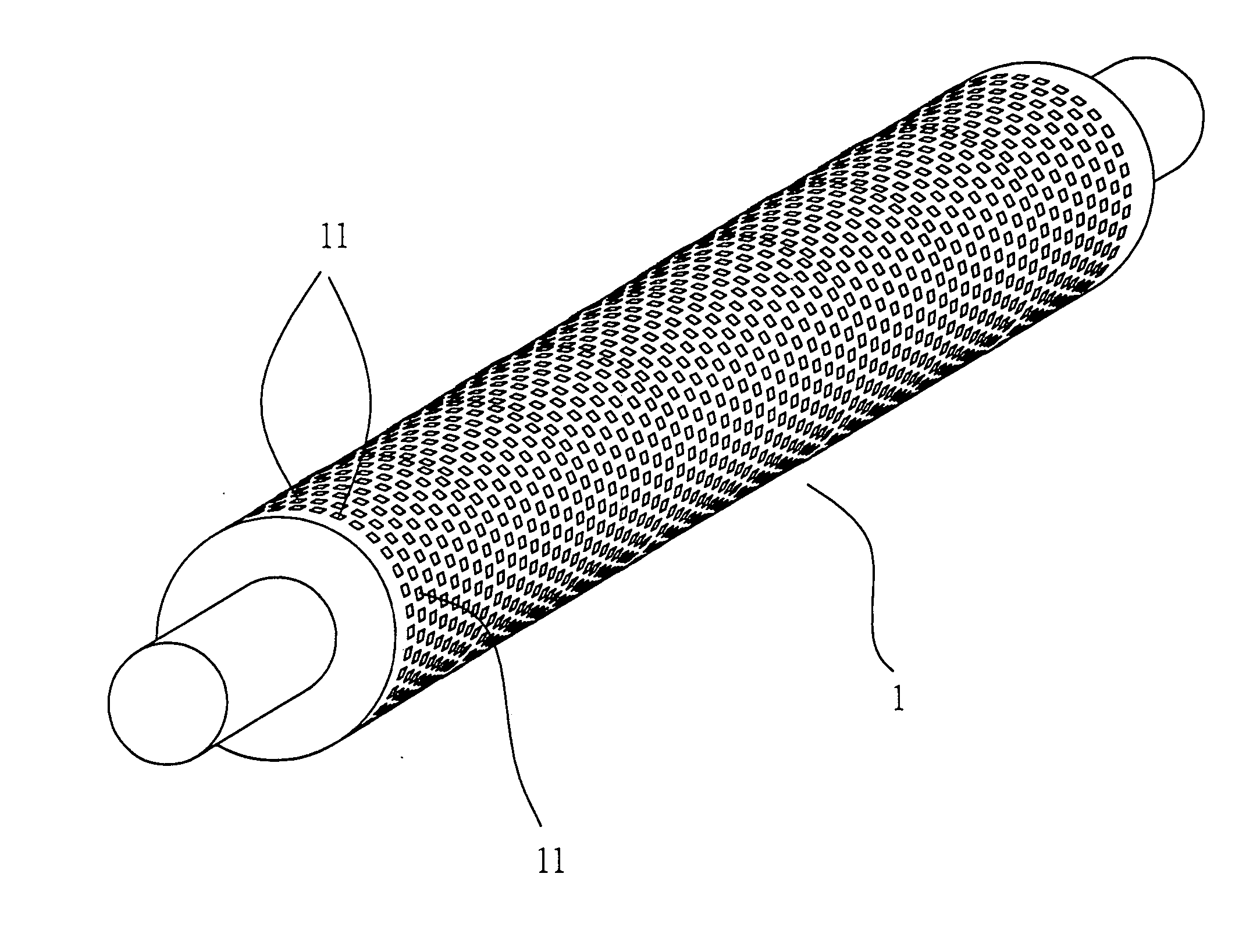
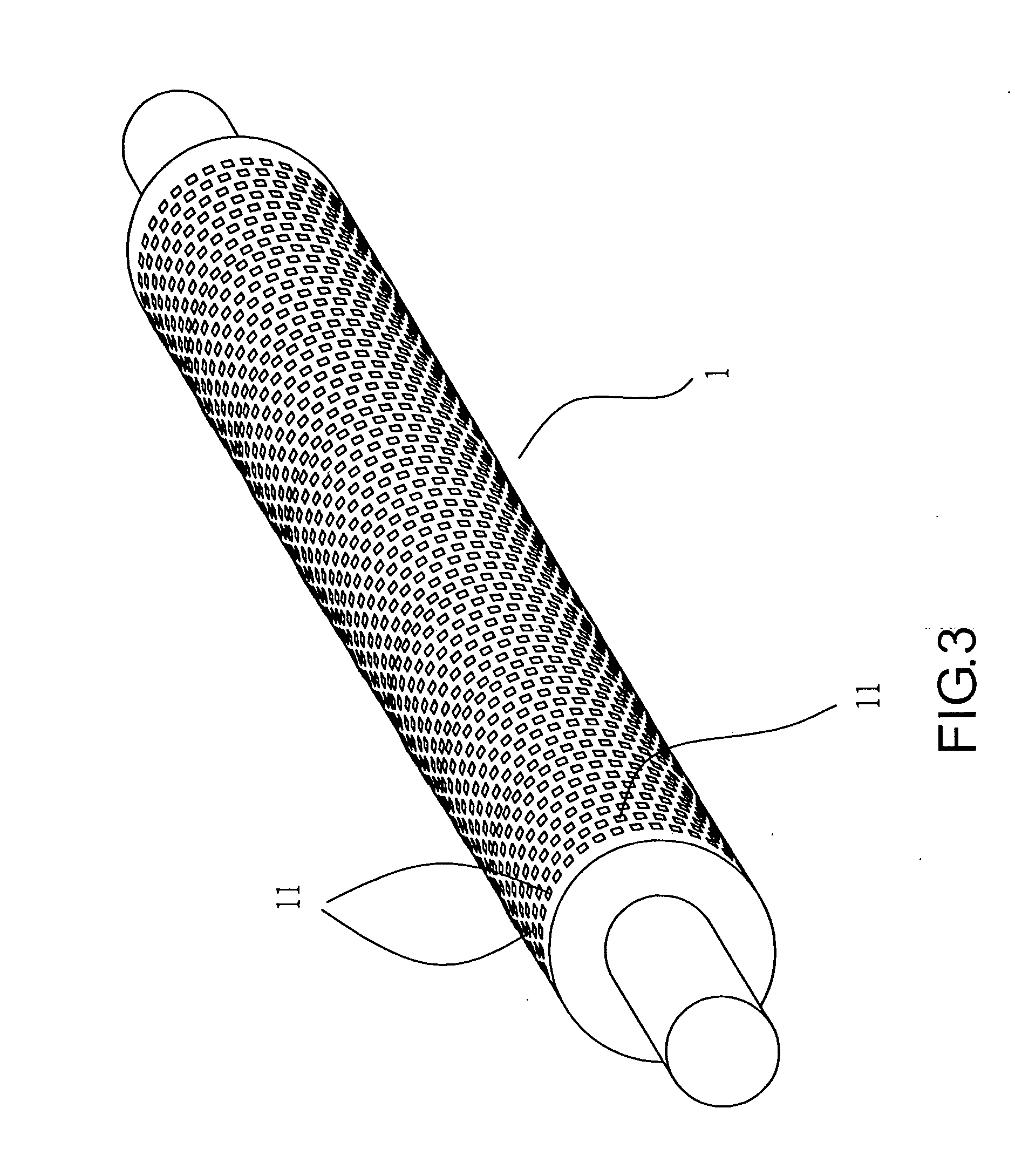
[0017] Referring to FIG. 3, which shows a schematic elevational view of an embodiment of the present invention, wherein a roller (1) is a non-plastic body, and requisite standard precisions are achieved during manufacture of a cylindrical body, such as degree of roundness of external diameter of the cylindrical body (tolerance of ±0.011 mms), and degree of skew (0.013 degrees), and so on. Such degrees of precision are established by measurement; accordingly, surface of the roller (1) is smooth when establishing the degrees of precision. However, the smooth surface of the roller (1) needs to possess friction, but without impairing the degrees of precision possessed by the roller (1), and employing a conventional method of covering and spraying a surface layer to fabricate a structural body is already known to create problems. Hence, the present invention adopts a totally different method to fabricate a structural body, namely a plurality of uniformly distributed etch points (11) are ...


PUM

PropertyMeasurementUnit
surface measurementsaaaaaaaaaa
frictionaaaaaaaaaa
frictional forceaaaaaaaaaa

Abstract

An etched type inkjet printer roller embodying a frictional surface that actuates conveying of paper sheets that is configured on a surface of the roller possessing standard precisions. The frictional surface is configured by employing etching technology that actualizes etch points below the standard precision surface, and which effectively preserves original degrees of precision possessed by the roller, thereby realizing convenience in manufacture of the roller, and ensuring requisite degrees of precision. The present invention improves upon shortcomings of current roller manufacturing processes that impair degrees of precision of the roller, creates enhanced effectiveness in functional practicability, and is a new model having practical value.

Description

BACKGROUND OF THE INVENTION [0001] (a) Field of the Invention [0002] The present invention relates to an etched type inkjet printer roller, and more particularly to the etched type inkjet printer roller provided with a frictional surface, and because etching method employed results in etch points that are below the surface of the roller, thus a structural body so configured preserves original degrees of precision possessed by the surface of the roller, which not only realizes convenient manufacture of the roller, moreover, achieves superior friction and degrees of precision for the surface of the roller, with the result that the roller is provided with functional practicability. [0003] (b) Description of the Prior Art [0004] A roller as utilized in a conventional ink jet printer is necessarily provided with a surface having substantial friction in order to actuate conveying of paper sheets, moreover, the roller possesses precision standards in degree of roundness and degree of skew....

Claims


Application Information

Patent Timeline
Patent Type & Authority Applications(United States)
IPC IPC(8): A01B29/00
CPCB41J13/02
Inventor CHOU, CHIH-HUANG
Owner CHOU CHIH HUANG
Why Eureka
Try Eureka