Check valve for pump of electronically controlled brake system

a technology of electronic control and check valve, which is applied in the direction of valve operating means/releasing devices, functional valve types, braking systems, etc., can solve the problems of unstable discharge pressure value of the outlet, b>i>b /i>, etc., to prevent leakage and variation in opening pressure, stabilize the discharge pressure value, and facilitate the fabrication of the valve piston

Inactive Publication Date: 2006-06-01
HYUNDAI MOBIS CO LTD
View PDF5 Cites 13 Cited by
  • Summary
  • Abstract
  • Description
  • Claims
  • Application Information

AI Technical Summary

Benefits of technology

[0013] Accordingly, the present invention has been made keeping in mind the above problems occurring in the prior art, and an object of the present invention is to provide a check valve for the pump of an electronically controlled brake system that has a structure capable of solving the problems of the conventional check valve by providing stable upward and downward movement without lateral movement.
[0015] With the above-described construction, the outer diameter of the valve piston comes into tight contact with the inner wall of the valve body and moves upward and downward without lateral movement, thus stabilizing discharge pressure value and preventing leakage and variation in opening pressure.
[0016] When the valve piston is fabricated by a plastic injection molding process, the fabrication of the valve piston is easy and the valve piston can smoothly move upward and downward without excessive frictional resistance.
[0017] Meanwhile, a fluid guide element for guiding influx fluid to the through hole is further formed, flow rate loss can be reduced and the outer diameter of the fluid guide element functions to come into tight contact with the valve body.
[0018] Furthermore, when a lip seal is formed on the fluid guide element, friction due to excessive compression does not occur, volume variation based on temperature variation is absorbed, and desired durability is excellent.
[0019] Furthermore, when a spring positioning portion is further formed on the valve piston, the performance and quality of the check valve can be prevented from being degraded.

Problems solved by technology

Meanwhile, the above-described check valve has the following problems.
First, when the ball 5 moves away from the contact surface of the valve body 3, the ball 5 moves laterally due to the gap between the inner wall 3d of the valve body 3 and the ball 5, so that the operation thereof is unstable, thus causing the discharge pressure value of the outlet 3b to be unstable.

Method used


Image

  • Check valve for pump of electronically controlled brake system
  • Check valve for pump of electronically controlled brake system
  • Check valve for pump of electronically controlled brake system

Examples


Embodiment Construction

[0023] Reference now should be made to the drawings, in which the same reference numerals are used throughout the different drawings to designate the same or similar components.

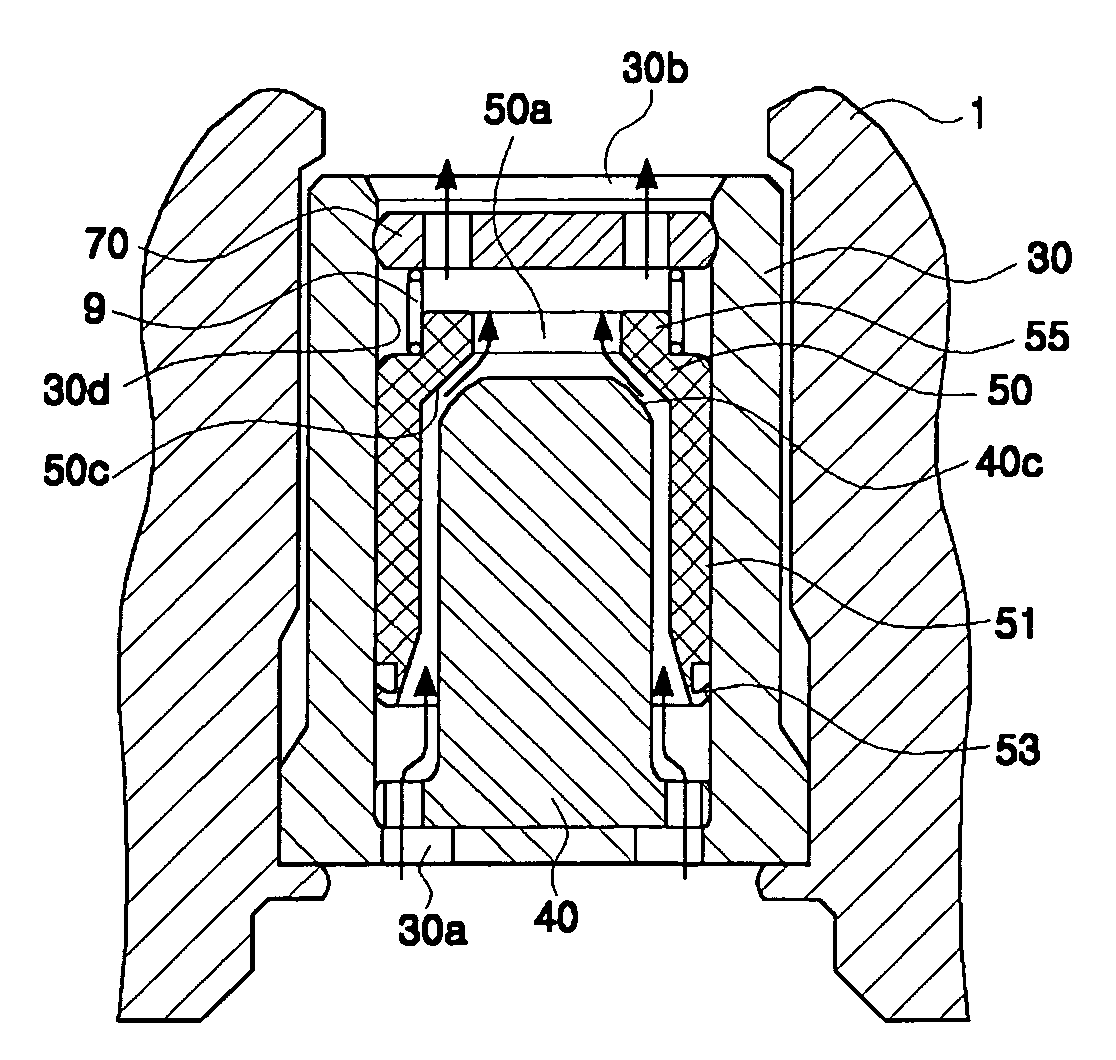
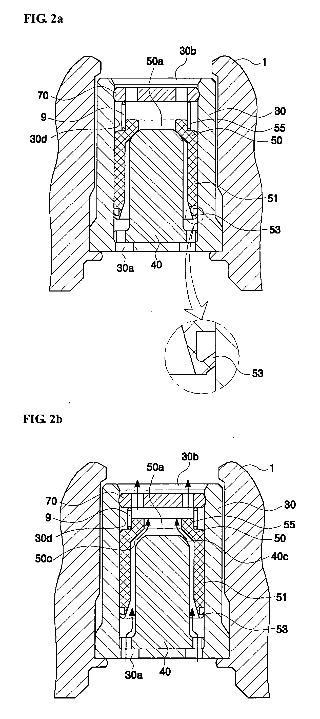
[0024]FIGS. 2a and 2b are sectional views showing the opening and closing positions of a piston type check valve, respectively, that is used in the pump of an electronically controlled brake system, in accordance with a preferred embodiment of the present invention.

[0025] The check valve according to the present invention, as shown in FIGS. 2a and 2b, includes a valve body 30 provided with a fluid path, a spring seat 70 placed in the outlet 30b of the flow path of the valve body 30, a valve rod 40 tightly fitted at the lower end thereof into the flow path inlet 30a of the valve body 30, a valve piston 50 selectively opened and closed by the valve rod 40 while moving upward and downward along the inner wall 30d of the valve body 30, and a spring 9 interposed between the spring seat 70 and the valve piston 50...


PUM


Abstract

A check valve for a pump of an electronically controlled brake system includes a valve body provided with a fluid path, a spring seat placed in an outlet of the fluid path of the valve body, a valve rod fitted at a lower end thereof into an inlet of the fluid path of the valve body, a valve piston provided with a through hole that is selectively opened and closed by an upper end of the valve rod, as the valve piston moves upward and downward along an inner wall of the valve body, and a spring interposed between the spring seat and the valve piston.

Description

RELATED APPLICATIONS [0001] The present disclosure relates to subject matter contained in priority Korean Application No. 10-2004-0099639, filed on Dec. 01, 2004, which is herein expressly incorporated by reference in its entirety. BACKGROUND OF THE INVENTION [0002] 1. Field of the Invention [0003] The present invention relates generally to a check valve for the pump of an electronically controlled brake system, such as an anti-lock brake system, a brake traction control system or a vehicle dynamic control system, and, more particularly, to a piston type check valve. [0004] 2. Description of the Related Art [0005] In general, an electronically controlled brake system is used to provide powerful and stable braking force by preventing an automobile from skidding. For such electronically controlled brake systems, there have been disclosed an Anti-lock Brake System (ABS) for preventing an automobile from skidding during the application of a brake, a Brake Traction Control System (BTCS) ...

Claims


Application Information

Patent Timeline
Patent Type & Authority Applications(United States)
IPC IPC(8): F16K15/02
CPCB60T8/341B60T8/4031F16K15/142F16K15/145Y10T137/7834Y10T137/7879Y10T137/7929Y10T137/7939B60T8/40
Inventor KWON, O-KYUN
Owner HYUNDAI MOBIS CO LTD
Why Eureka
Try Eureka