Method of making an ocular implant

Inactive Publication Date: 2006-06-01
ACUFOCUS
View PDF99 Cites 121 Cited by
  • Summary
  • Abstract
  • Description
  • Claims
  • Application Information

AI Technical Summary

Benefits of technology

[0011] In another embodiment, a method of making a mask configured to improve the depth of focus of an eye of a patient is provided. A substrate with a mask forming feature is provided. The mask forming feature comprises a forming surface that is centered on a central axis of the mask forming feature. A release layer is formed on the annular surface. A mask layer is formed such that the release layer is between the mask layer and the substrate. The mask layer is formed of a biocompatible metal. A surface of the mask layer opposite the release layer is configured to not corrode. The mask layer is separated from the substrate.
[0012] In another embodiment, a method of making a mask configured be implanted in a cornea of an eye of a patient to improve the depth of fo

Problems solved by technology

Presbyopia may be caused by defects in the focusing elements of the eye or the inability (due to aging) of the ciliary muscles to contract and relax and thereby control the shape of the lens in the eye.
However, if the cornea or the lens are not functioning properly, or are irregularly shaped, the

Method used


Image

  • Method of making an ocular implant
  • Method of making an ocular implant
  • Method of making an ocular implant

Examples


Embodiment Construction

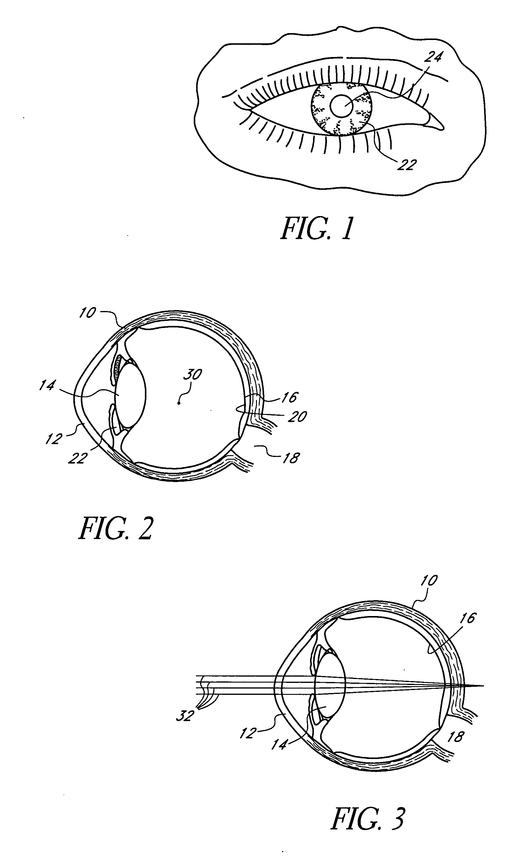
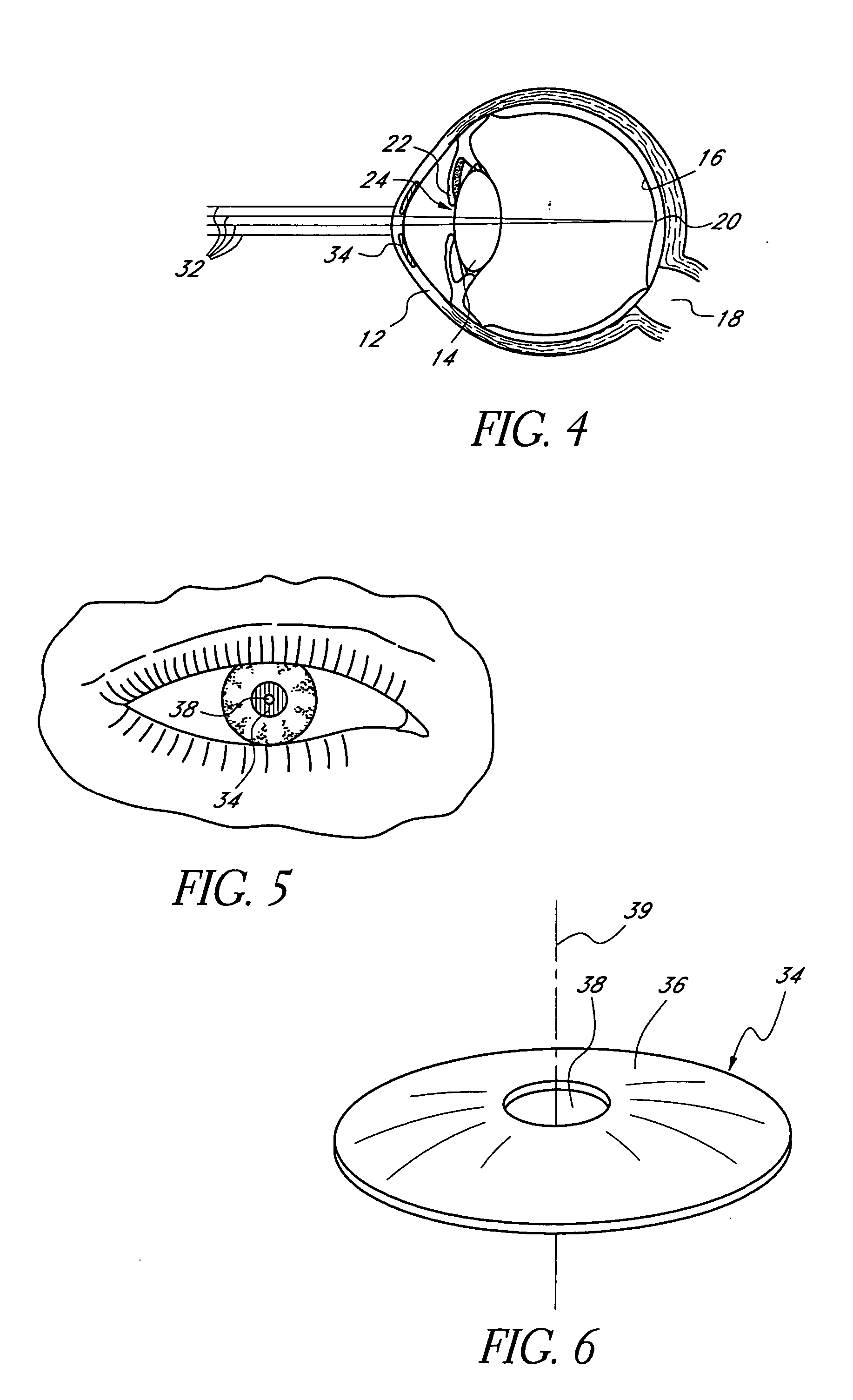
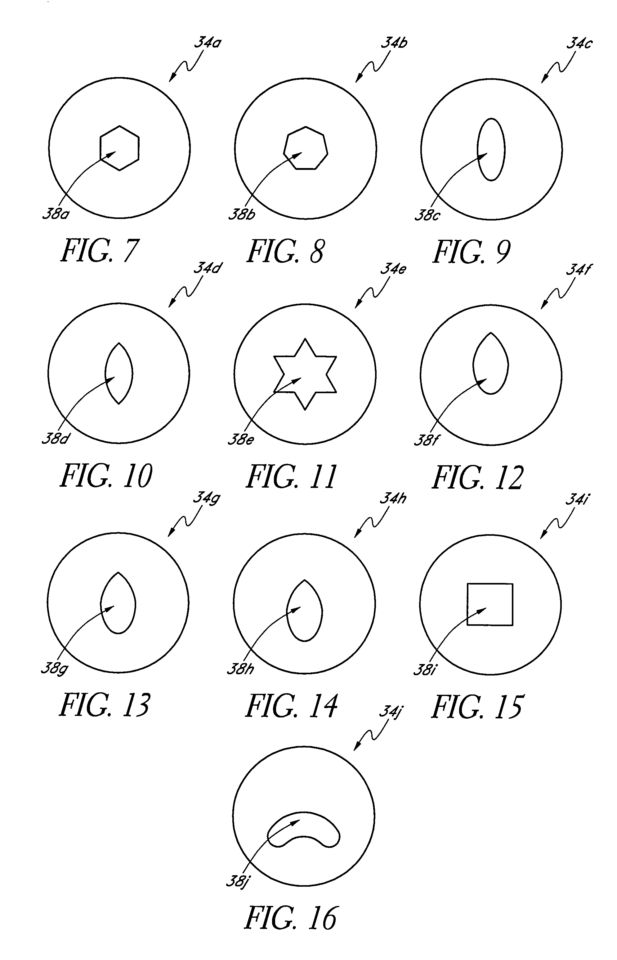
[0100] This application is directed to masks for improving the depth of focus of an eye of a patient using pin-hole imaging and methods and apparatuses for making such masks. The masks may be applied to the eye in any manner and in any location, e.g., as an implant in the cornea (sometimes referred to as a “corneal inlay”). As discussed further below, some methods for making such masks employ techniques that deposit thin films of material. The materials used to make the mask can be metals that are selected or configured for long-term or permanent implantation. Some metals are subject to processes, such as corrosion, that can degrade a mask over time. As discussed further below, the mask can be formed of a material that is stable, e.g., one that is not subject to such processes or that substantially resists such processes. In some embodiments, the mask is formed of a material that is selected or configured to be inert, e.g., to not degrade due to physical or chemical processes such a...


PUM

PropertyMeasurementUnit
Densityaaaaaaaaaa
Depthaaaaaaaaaa
Elasticityaaaaaaaaaa

Abstract

A method of making a mask configured to improve the depth of focus of an eye of a patient is provided. A substrate with a mask forming feature is provided. The mask forming feature comprises a forming surface that extends from an outer periphery. The forming surface is centered on a central axis of the mask forming feature. A release layer is formed on the forming surface. A mask layer is formed such that the release layer is between the mask layer and the substrate. The mask layer is formed of a biocompatible metal. A surface of the mask layer opposite the release layer is configured to not corrode. The mask layer is separated from the substrate.

Description

CROSS-REFERENCE TO RELATED APPLICATIONS [0001] This application is a continuation in part of U.S. application Ser. No. 11 / 000,562, filed Dec. 1, 2004, the entire contents of which is hereby expressly incorporated by reference herein.BACKGROUND OF THE INVENTION [0002] 1. Field of the Invention [0003] This application is directed to masks for improving the depth of focus of an eye of a human patient. This application also is directed to apparatuses and methods to produce masks that are resistant to corrosion, or other decay or degradation when applied to a patient. [0004] 2. Description of the Related Art [0005] Presbyopia, or the inability to clearly see objects up close is a common condition that afflicts many adults over the age of 40. Presbyopia diminishes the ability to see or read up close. Near objects appear blurry and out of focus. Presbyopia may be caused by defects in the focusing elements of the eye or the inability (due to aging) of the ciliary muscles to contract and rel...

Claims


Application Information

Patent Timeline
IPC IPC(8): B22D23/00
CPCA61F2/0059A61F2/14A61F2250/0014C23C14/0005C23C16/01A61F2240/001A61F2/15
Inventor SILVESTRINI, THOMAS A.
Owner ACUFOCUS
Why Eureka
Try Eureka