Dual-frequency hollow focused ultrasonic detector

A technology for focusing ultrasound and detectors, which is applied in ultrasonic/sonic/infrasonic diagnosis, acoustic diagnosis, infrasonic diagnosis, etc. Axis, difficult to extract the tissue information of the detected part, etc., to achieve the effect of improving resolution and detection sensitivity, good imaging effect, and increasing the depth of focus

Inactive Publication Date: 2016-08-31
广州佰奥廷电子科技有限公司
View PDF5 Cites 17 Cited by
  • Summary
  • Abstract
  • Description
  • Claims
  • Application Information

AI Technical Summary

Problems solved by technology

[0003] At present, most of the ultrasonic detectors for photoacoustic imaging are non-hollow ultrasonic detectors, which cannot ensure that the incident light is coaxial with the ultrasonic detector, so that it is difficult to improve the resolution and detection sensitivity of the microscopic imaging system. The effective transmission, the image effect can not achieve the best; although there are ultrasonic detectors using a hollow mode, but it is inconvenient to couple with the surface of the detected part during work, so it is not fully suitable for the clinical application of photoacoustic microscopy instruments; and , the frequency band of the existing ultrasonic detector is relatively narrow, it is difficult to extract more tissue information of the detected part

Method used


Image

  • Dual-frequency hollow focused ultrasonic detector
  • Dual-frequency hollow focused ultrasonic detector
  • Dual-frequency hollow focused ultrasonic detector

Examples


Embodiment Construction

[0021] In order to facilitate the understanding of the present invention, the present invention will be described more fully below with reference to the relevant drawings. The preferred embodiments of the invention are shown in the drawings. However, the present invention can be implemented in many different forms and is not limited to the embodiments described herein. On the contrary, the purpose of providing these embodiments is to make the understanding of the disclosure of the present invention more thorough and comprehensive.

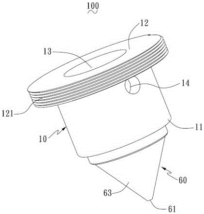
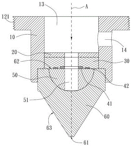
[0022] Such as figure 1 with figure 2 As shown, the dual-frequency hollow focused ultrasound probe 100 of a preferred embodiment of the present invention includes: a cylindrical housing 10, an acoustic focusing lens, a ring-shaped sound-absorbing material layer 20, a ring-shaped backing material layer 30, and a ring-shaped ultrasound The transducer and the signal line electrically connected to the ultrasonic transducer (not shown). The housing 10 h...


PUM


Abstract

The invention relates to a dual-frequency hollow focused ultrasonic detector. The detector comprises a cylindrical shell, an acoustic focusing lens arranged in the shell, an annular sound absorption material layer, an annular back lining material layer, annular ultrasonic transducers and a signal line, wherein the annular sound absorption material layer and the annular back lining material layer are arranged in the shell in an overlapped mode, the annular ultrasonic transducers are arranged on the back lining material layer and face the acoustic focusing lens, and the signal line is electrically connected with the ultrasonic transducers. A line outlet for leading out the signal line is formed in the sidewall of the shell. The acoustic focusing lens comprises a semispherical first lens part and a similar-conical second lens part, an incident laser is coaxial with the detector, the resolution is enhanced, the detection sensitivity is improved, and the imaging effect is good; by means of the first lens part and the second lens part adopting two different acoustic-impedance acoustic materials, photo-acoustic signal collimation is achieved, acoustic focusing is achieved, and the acoustic resolution is enhanced. The ultrasonic transducers with two different dominant frequencies are adopted, the wide-band performance of the dual-frequency hollow focused ultrasonic detector is improved, and more pathologic messages of a detected portion in the transverse direction and the longitudinal direction can be obtained.

Description

Technical field [0001] The invention relates to the technical field of photoacoustic imaging, in particular to a dual-frequency hollow focused ultrasound detector. Background technique [0002] Photoacoustic imaging is a new type of non-destructive biomedical imaging technology developed in recent years. It combines the high contrast of pure optical imaging and the high resolution of pure ultrasound imaging. The imaging technology uses short-pulse laser as the excitation source, and the ultrasound signal excited thereby as the information carrier, and uses the corresponding image reconstruction algorithm to reconstruct the internal structure and function of the tissue. This technology combines the characteristics of optical imaging and acoustic imaging to provide high-resolution and high-contrast tissue tomography images of deep tissues. It has broad application prospects in the field of biomedical clinical diagnosis and in vivo imaging. [0003] At present, most of the ultrasound...

Claims


Application Information

Patent Timeline
Patent Type & Authority Applications(China)
IPC IPC(8): B06B1/06A61B8/00
CPCA61B8/00B06B1/0688
Inventor 许栋马海钢纪轩荣
Owner 广州佰奥廷电子科技有限公司
Why Eureka
Try Eureka