Distributed wireless access method based on network allocation vector table and apparatus of the same

a wireless access and network allocation technology, applied in the field of distributed wireless access methods and apparatuses, can solve the problems of system resource waste, system performance degradation, exposed terminals, etc., and achieve the effect of improving system throughput and resource utilization rate, and reducing packet collision and resource was

Active Publication Date: 2006-06-01
NTT DOCOMO INC
View PDF3 Cites 69 Cited by
  • Summary
  • Abstract
  • Description
  • Claims
  • Application Information

AI Technical Summary

Benefits of technology

[0013] Embodiments of the present invention include a distributed wireless medium access control method, which is capable of reducing the packet collision and the waste of resources by solving the hidden terminal problem and the exposed terminal problem in the distribute wireless network, to thereby improve the system throughput and the utilization rate of resource.

Problems solved by technology

However, since centralized control device is absent for performing resource allocation in a unified way, respective nodes independently control the transmission of their packets, and the problems due to hidden / exposed terminals occurring in the distributed network have become the main factors for affecting performance.
That is, when two transmitting nodes are not within the sensing range of each other, and send packets to a same receiving node independently, a collision will occur between packets from the two different transmitting nodes at the receiving node, thereby leading to the degradation of the system performance.
This leads to a waste of system resources and causes the exposed terminal problem.
Specifically, as shown in FIG. 1A, node B is located within the communication ranges of node A and node C, and node C is not located within the communication range of node A. If node A and node C send their respective dada packet to node B concurrently, a collision of these two data packets would occur at node B. This leads to the hidden terminal problem.
Although 802.11 DCF has solved the hidden terminal problem, allowing the system performances to be improved as compared with the conventional distributed access modes such as CSMA, the problems such as the exposed terminal still restrict further improvement on the utilization rate of system resources.
This causes waste of radio resources.
However, in fact, receiving the data from the node E by node F would not cause a disturbance on receiving the data from node A by node B, thereby leading to the waste of resources and further leading to the unnecessary retransmissions when node E receives no response to the RTS.
As such, although the conventional medium access control method based on the NAV reduces the collision caused by the hidden terminal to a certain degree at the receiving nodes, the above problems are still not solved and there is still a space for improving the utilization rate of system resources.

Method used


Image

  • Distributed wireless access method based on network allocation vector table and apparatus of the same
  • Distributed wireless access method based on network allocation vector table and apparatus of the same
  • Distributed wireless access method based on network allocation vector table and apparatus of the same

Examples


first embodiment

The First Embodiment

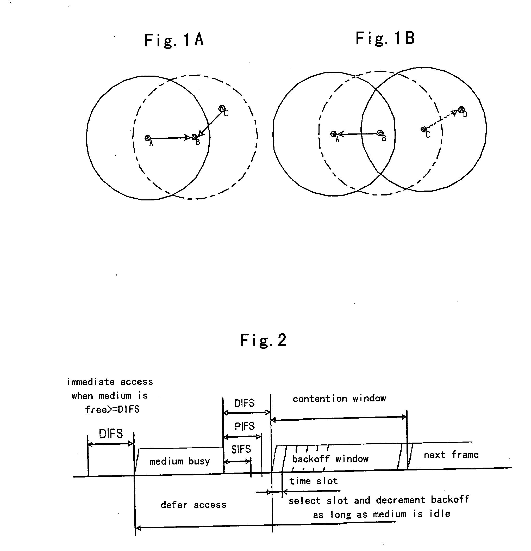
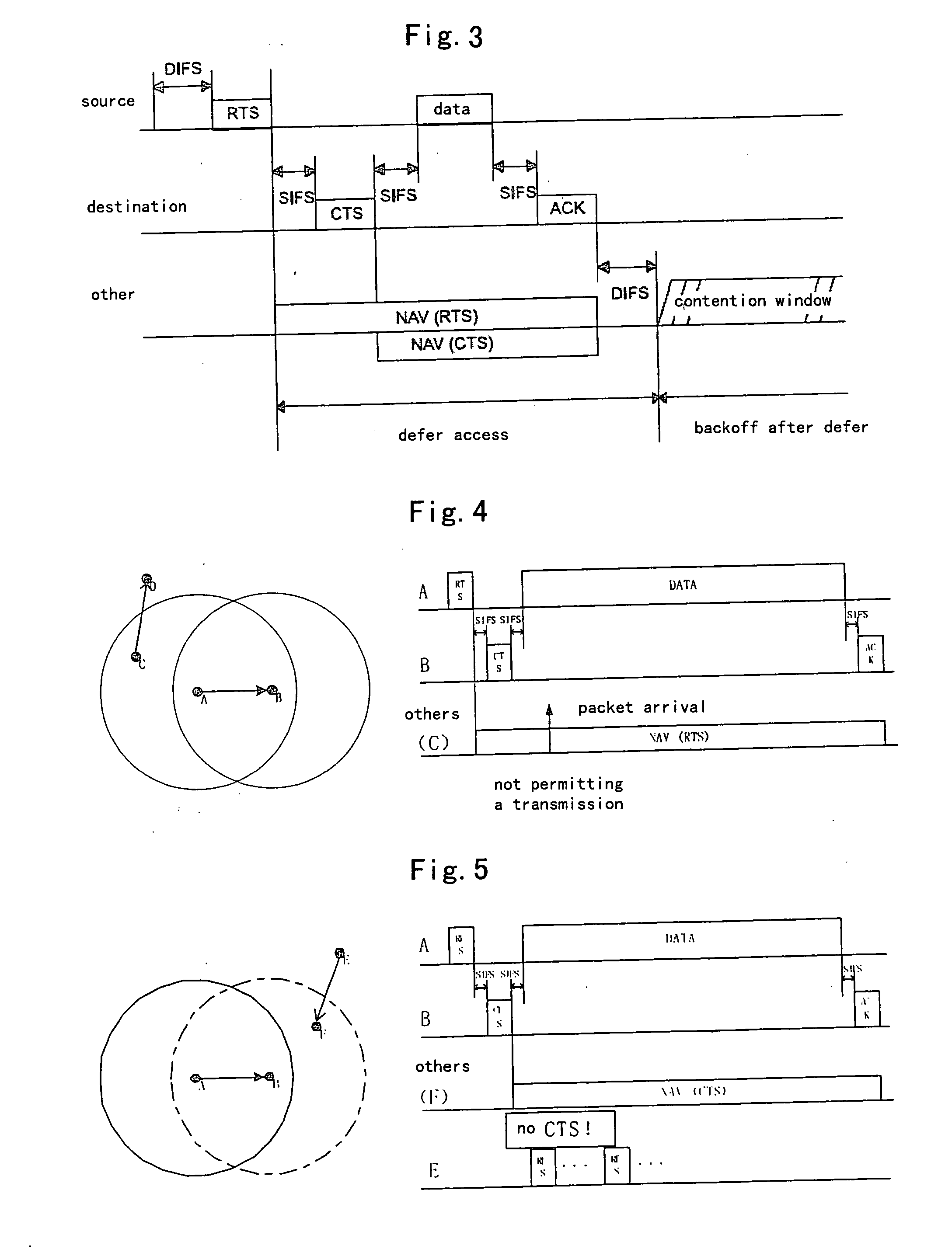
[0103]FIG. 13 is a diagram illustrating node distribution in the distributed wireless network according to the first, the second and the third embodiments of the present invention. In the FIG. 13, node A and node B are within the communication range of each other; node C is within the communication range of node A but not within the communication range of node B; and node D is not within the communication range of any nodes. Node A is to transmit a packet to node B; and node C is to transmit a packet to node D. The NAVT table is empty when a packet arrives in node A, and the NAVT table in node B is also empty.

[0104]FIG. 14 is a diagram illustrating timing sequence of the access method based on the NAVT without RTS / CTS exchange when node distribution is as shown in FIG. 13 in the case of no channel splitting.

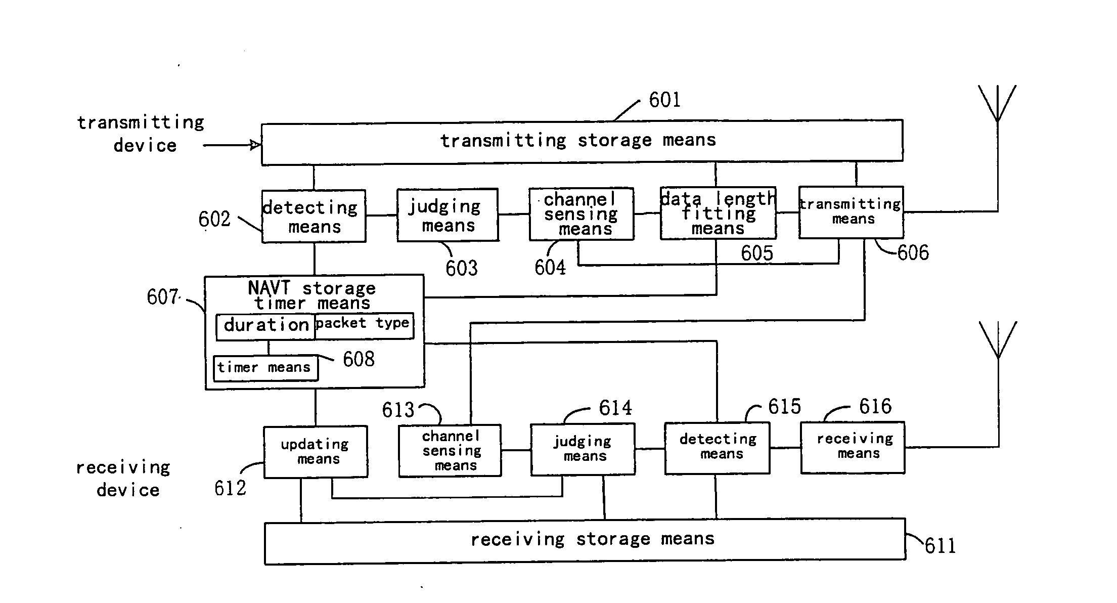
[0105] At time to, a packet arrives at the transmitting storage unit 601 in node A. Node A detects that the packet arrives and the current NAVT is empty by ...

second embodiment

The Second Embodiment

[0115]FIG. 15 is a diagram illustrating timing sequence of the access method based on the NAVT with RTS / CTS exchange when the node distribution is as shown in FIG. 13 in the case of no channel splitting.

[0116] In the present embodiment, the operations concerning nodes A and B are the same as those in the first embodiment, the description of which is omitted herein.

[0117] At time t5, a packet arrives in node C. At this time, node C detects the arrival of packet by using the detecting unit 602, and further detects that only RTS item is indicated in its NAVT. The NAVT of node C at time t5 is shown in the third line on the right side of FIG. 15, wherein TAB—RTS—t5 indicates the value at time t5 under the control of the NAVT storage timer unit 607. Node C enters the channel sensing unit 604 via the determination unit 603, performs a data length fitting upon sensing that the channel is busy, and transmits the RTS2 packet by using the transmitting unit 606 based on t...

third embodiment

The Third Embodiment

[0123]FIG. 16 is a diagram illustrating timing sequence of the access method based on the NAVT with RTS / CTS exchange when node distribution is as shown in FIG. 13 in the case of channel splitting.

[0124] At time t0, a packet arrives at the transmitting storage unit 601 in node A. Node A detects that the packet arrives and the current NAVT is empty by using the detecting unit 602, and sends the determination result from the determination unit 603 into the channel selecting unit 707 to select the SCH. The SCH channel is sensed by the channel sensing unit 704. When it is sensed that the SCH channel is idle in the DIFS interval, the SCH channel is maintained by the channel selecting unit 708, and the RTS packet is started to send on the SCH by the transmitting unit 706 at time t1. The description of the partial fields in the RTS packet transmitted by node A is shown in the first line on the right side of FIG. 16, wherein the value of the duration field is TAB—RTS, in...


PUM


Abstract

Embodiments of the present invention include a wireless access method based on a NAVT (Network allocation vector table), which is applied to a distributed wireless mobile communication system comprising a plurality of nodes, the NAVT comprises a packet type field and a duration field and is stored in the respective nodes of the communication system, comprising: on a transmitting side, determining whether only a RTS (request to send) item is contained in the NAVT when a packet arrives; sensing channel to judge whether the channel is busy after determining that only the RTS item is contained in the NAVT; sending a RTS packet based on the RTS item to the receiving side after determining that the channel is busy; and on a receiving side, determining whether the NAVT is empty or not when the RTS packet is received; sending a CTS (clear to send) packet back to the transmitting side after determining that the NAVT is empty.

Description

PRIORITY [0001] The present patent application claims priority to and incorporates by reference the corresponding Chinese patent application serial no. 200410009867.X, titled, “Distributed Wireless Access Method Based on Network Allocation Vector Table and Apparatus of the Same,” filed on Nov. 25, 2004. BACKGROUND OF THE INVENTION [0002] 1. Field of the Invention [0003] This invention relates to a wireless medium access control (MAC) technique. More specifically, the invention relates to a distributed wireless access method and apparatus based on a network allocation vector table which is applicable to point to point communication in a distributed wireless network, in order to improve the performances, such as throughput, of the system by solving the hidden / exposed terminal problems occurring in the wireless distributed network. [0004] 2. Description of the Prior Art [0005] The wireless medium access control (MAC) technique can be classified into centralized control mode and distrib...

Claims


Application Information

Patent Timeline
Patent Type & Authority Applications(United States)
IPC IPC(8): H04Q7/24H04W16/14H04W24/00H04W72/04H04W72/08H04W74/00H04W74/08H04W84/12H04W99/00
CPCH04W28/06H04W74/002H04W74/0808
Inventor DU, LEICHEN, LAN
Owner NTT DOCOMO INC
Why Eureka
Try Eureka