
Excavating machine for rocky and other soils

a technology of excavating machine and soil, which is applied in the direction of mechanical machine/dredger, soil shifting machine/dredger, construction, etc., can solve the problems of ineffective excavating of spoil from a trench, large mass of crawler tractors, and inability to drive on hard surface roadways, etc., to reduce the mass of drive tractors, operate more efficiently, and efficiently remove spoil

Inactive Publication Date: 2006-06-08
YODER SHAUN LAMAR
View PDF18 Cites 3 Cited by
  • Summary
  • Abstract
  • Description
  • Claims
  • Application Information

AI Technical Summary

Benefits of technology

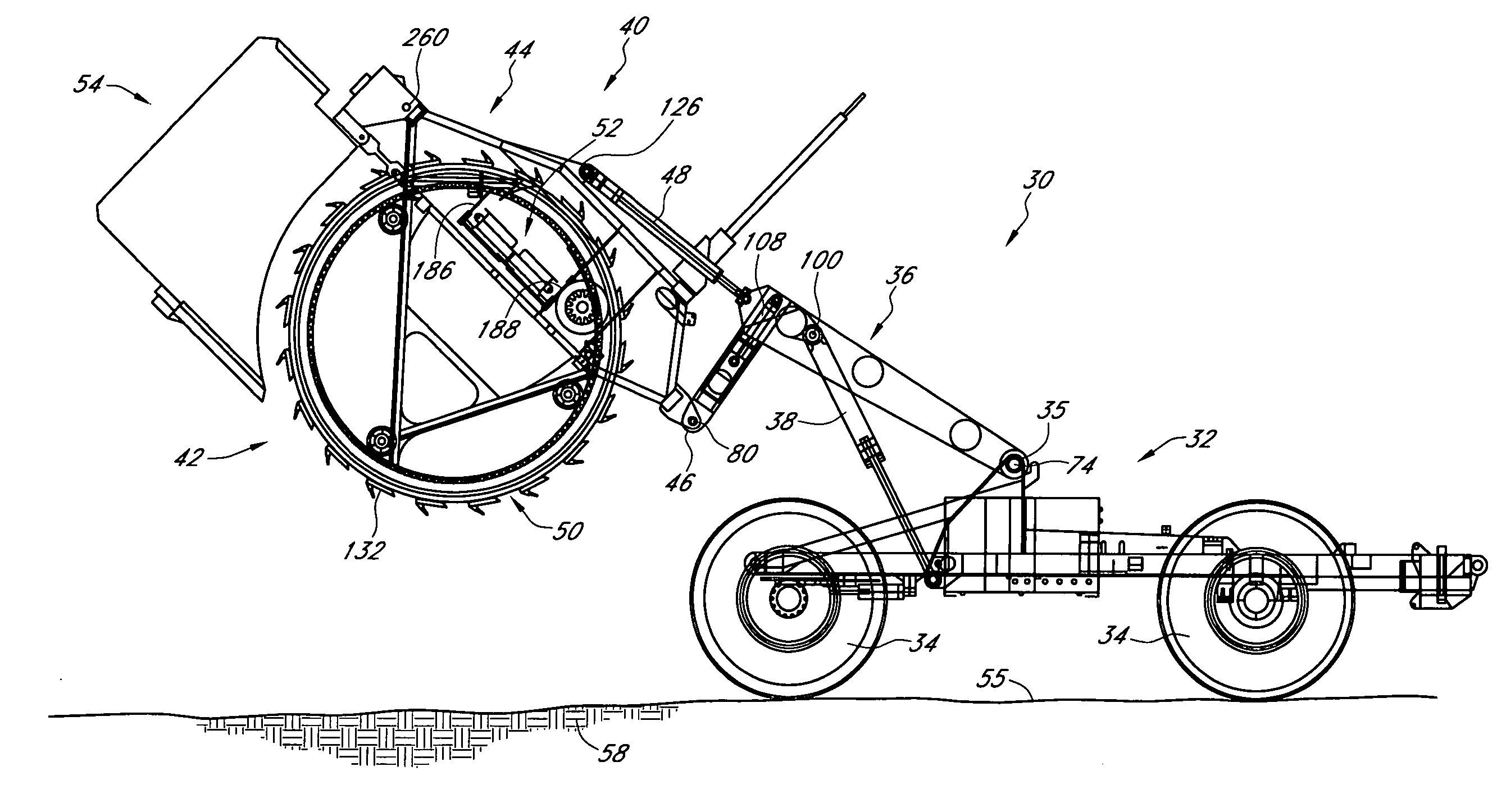
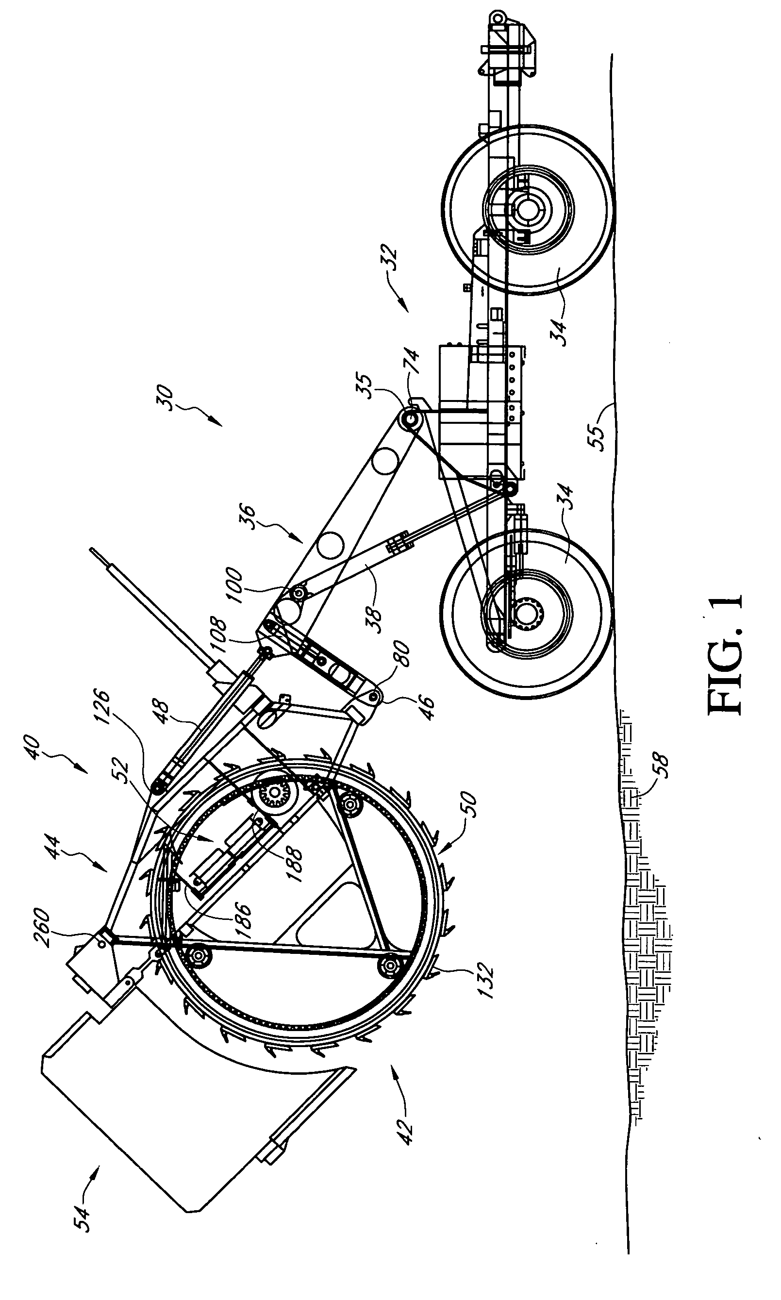
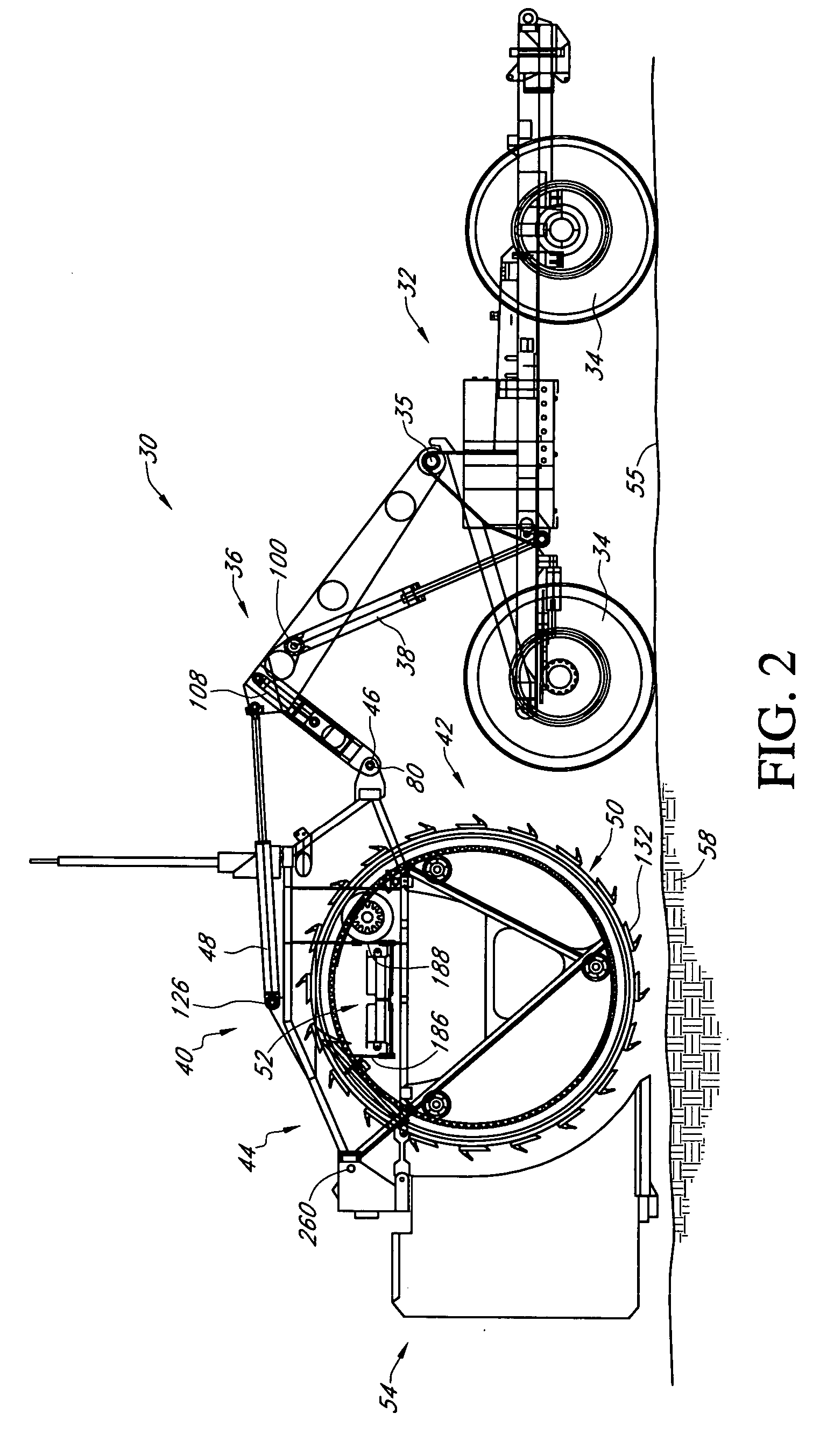
[0007] The excavator is equipped with an L-shaped lifting arm to which the excavating wheel assembly is mounted which allows the excavating wheel assembly and associated shoe member to be raised or lowered at the rear of the drive unit or tractor. The L-shaped lifting arm allows downward force to be applied to the wheel assembly. A transverse conveyor is located within the circumference of the wheel such that spoil carried over the top of the wheel may drop on the conveyor and be moved to the side of the trench being excavated. A cleaning member with a cleaning face is located at the top of the digging wheel in such a manner that it removes the spoil which has accumulated in the rim structure of the digging wheel and directs the spoil downwardly onto the conveyor.
[0008] A shoe member follows the trenching wheel through the trench being excavated. The shoe member in cooperation with the L-shaped lifting arm provides a fulcrum for downward force placed on the L-shaped arm by hydraulic cylinders, thereby forcing the excavating wheel into the trench and reducing the mass of the drive tractor needed to hold the wheel in the trench. The drive unit is carried on wheels with tires which permit the machine to be transported under its own drive power on a roadway.
[0009] Accordingly, it is an object of the present invention to provide an excavating machine which can trench through rocky soil as well as through non-rocky soil.
[0010] It is a further object of the present invention to provide an excavating machine which can be operated more efficiently.
[0011] It is also an object of the invention to provide an excavating machine which can be driven at reasonable roadway speeds on hard surface roadways.
[0012] An additional object of the present invention is to provide an excavating machine which efficiently removes spoil from the trench being excavated.

Problems solved by technology

Existing excavating machines usually employ earth cutting buckets or shovels for cutting into the earth and removing spoil from the trench being made but these elements do not function well when rocks within the earth to be trenched are encountered.
Circular saws have been utilized for cutting through rocky soils but these machines do not effectively excavate spoil from a trench.
In addition, most trenching excavators are mounted on crawler tractors and are of very large mass and cannot be driven on hard surface roadways without damage to the roadway being traversed.

Method used


Image

  • Excavating machine for rocky and other soils
  • Excavating machine for rocky and other soils
  • Excavating machine for rocky and other soils

Examples


Embodiment Construction

[0040] This invention discloses an improved excavating machine for cutting a trench through the earth. The invention particularly discloses an improved excavating machine for trenching through rocky soils. Prior improvements to wheel trenchers invented in whole or in part by one of the instant inventors are shown in U.S. Pat. Nos. 4,890,670; 5,873,186; 5,943,798; and 6,055,750; the disclosures of each of which are incorporated herein by this reference.

[0041] Referring to FIG. 1, the numeral 30 generally designates the excavating machine of the present invention. The excavating machine 30 includes a power unit vehicle 32 supported by wheels 34. Pivotally mounted about a horizontal axis 35 on the power unit vehicle 32 is an L-arm assembly 36 which is adapted to be raised and lowered by means of a hydraulic cylinder 38. Pivotally mounted to the L-arm assembly 36 is earth cutting assembly 40. The earth cutting assembly 40 of the preferred embodiment comprises a rock wheel trencher asse...


PUM


Abstract

A trench excavating machine includes an excavating wheel on which are mounted spaced apart peripheral plates equipped with ripping teeth and spades. The ripping teeth are angled outward from the plates at an acute angle directed in the direction of rotation of the cutting wheel to attack the leading edge of a trench being excavated. Ripping teeth and spades are arranged at varying spacing on succeeding plates about the centerline of the cutting wheel. A transverse conveyor located within the circumference of the cutting wheel transports spoil to the side of the cutting wheel. A spoil deflector removes spoil adhered to the inside of the cutting wheel.

Description

CROSS-REFERENCE TO RELATED APPLICATIONS [0001] This application claims priority from copending provisional patent application entitled “Excavating Machine for Rocky and Other Soils,” Ser. No. 60 / 634,323 filed Dec. 8, 2004. The disclosure of provisional patent application Ser. No. 60 / 634,323 is hereby incorporated in its entirety.BACKGROUND OF THE INVENTION [0002] The invention relates generally to excavating machines of the type having a device for cutting the earth including bucket wheel trenchers, chain bar trenchers, trencher or trenchless plows and hoes, vibratory plows, disc wheel cutters, drum cutters, etc., and more particularly to a cutting plate carried on the trenching wheel or chain for breaking through rocky soils. [0003] Excavating machines are well known for use in the cutting of an open trench having either vertical or sloped walls for the purposes of land drainage and irrigation including agricultural tiling, as well as the installation of utilities such as cable lin...

Claims


Application Information

Patent Timeline
Patent Type & Authority Applications(United States)
IPC IPC(8): E02F5/08
CPCE02F3/181E02F3/188E02F3/20E02F5/08E02F7/02
Inventor YODER, SHAUN LAMARHOLTMEIER, JERRY
Owner YODER SHAUN LAMAR
Learn More