Thermoelectric direct conversion device

a conversion device and thermal technology, applied in the direction of thermoelectric device details, thermoelectric device with peltier/seeback effect, electric apparatus, etc., can solve the problems of inability to achieve the quantity of electricity compensating for the cost of modification of existing facilities and maintenance and repair costs, and achieve excellent power generation performan

Inactive Publication Date: 2006-06-08
KK TOSHIBA
View PDF6 Cites 83 Cited by
  • Summary
  • Abstract
  • Description
  • Claims
  • Application Information

AI Technical Summary

Benefits of technology

[0028] In the thermoelectric direct conversion device according to the present invention, the diffusion through a boundary between a

Problems solved by technology

However, waste heat in a small to a medium scale is relatively low in calories, even if it is of high quality.
Accordingly, if a large-scale electric power plant for waste heat, such as a steam turbine, for example, applied thereto, huge equipment is required for such a small amount of heat, so that the power generation efficiency becomes extremely low, and a quantity of electricity compensating for the costs of the modification of existing facilities and the maintenance and repair costs, cannot be attained.
Furthermore, utilization of a heat source, such as hot water, is not realized in many cases, owing to the small amount of calories.
Thus, it is a present state throughout the world that the utilization of waste heat in a small to a medium scale cannot be readily advanced.
However, when the thermoelectric direct conversion device shown in FIG. 13 is used in such a high-temperature atmosphere, a component through which the electric current flows,

Method used


Image

  • Thermoelectric direct conversion device
  • Thermoelectric direct conversion device
  • Thermoelectric direct conversion device

Examples


first embodiment

(1) Structure of Thermoelectric Direct Conversion Device

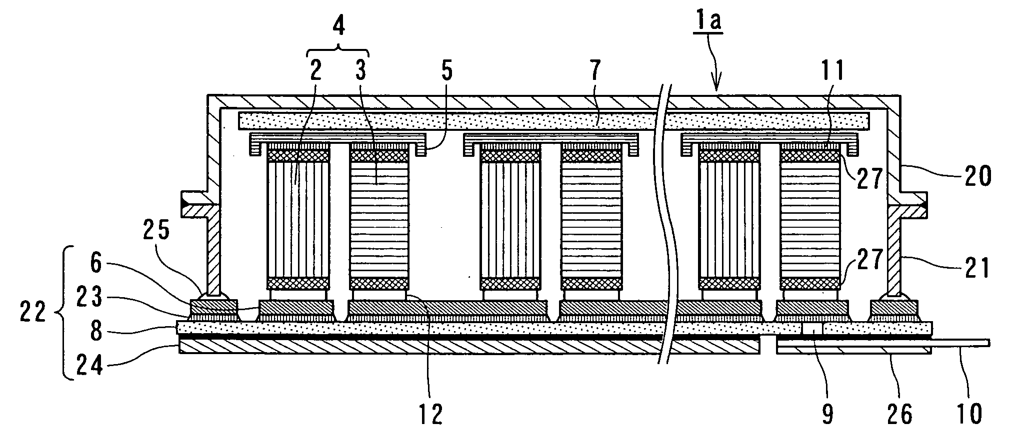
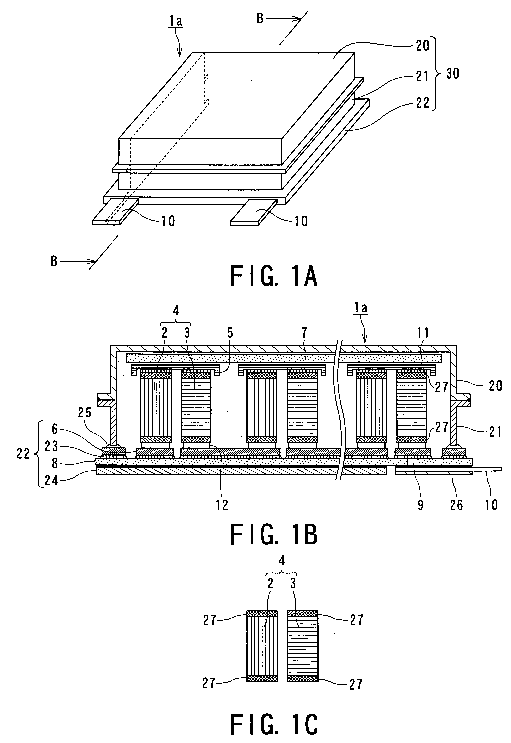
[0033]FIG. 1 illustrates a thermoelectric direct conversion device according to a first embodiment of the present invention.

[0034]FIG. 1A is a schematic perspective view of a thermoelectric direct conversion device 1a according to the first embodiment of the present invention. FIG. 1B is a schematic cross-sectional view of the thermoelectric direct conversion device 1a, taken along the line B-B in FIG. 1A. FIG. 1C is a schematic view of a thermoelectric direct conversion semiconductor pair 4 shown in the thermoelectric direct conversion device 1a.

[0035] As shown in FIG. 1, the thermoelectric direct conversion device 1a includes a plurality of thermoelectric direct conversion semiconductor pairs 4 for directly converting thermal energy to electrical energy or electrical energy to thermal energy, and an airtight case 30 for isolating the thermoelectric direct conversion semiconductor pairs 4 from the environmental atmosphere.

[...


PUM


Abstract

A thermoelectric direct conversion device is foemed of a plurality of thermoelectric direct conversion semiconductor pairs each including a p-type semiconductor and an n-type semiconductor; a plurality of high-temperature electrodes and a plurality of low-temperature electrodes each electrically connecting the p-type semiconductor and the n-type semiconductor; a high-temperature insulating plate and a low-temperature insulating plate each thermally connected to the plurality of thermoelectric direct conversion semiconductor pairs via the plurality of high-temperature electrodes and the plurality of low-temperature electrodes, respectively; at least one diffusion barrier layer is disposed between the high- or low-temperature electrodes and the thermoelectric direct conversion semiconductor pairs, and the entire device is hermetically sealed up within an airtight case containing a vacuum or inert gas atmosphere, whereby diffusion between the electrodes and the semiconductor pairs is prevented to provide a thermoelectric conversion devise exhibiting excellent power generation performances for a long time period.

Description

BACKGROUND OF THE INVENTION [0001] 1. Field of the Invention [0002] The present invention relates to a thermoelectric direct conversion device, and particularly to a thermoelectric direct conversion device that can maintain the mechanical characteristics or the electrical characteristics of its components and excellent conversion efficiency over a long period of time. [0003] 2. Description of the Related Art [0004] An unprecedentedly rapid increase in the energy consumption in recent years has caused global warming due to the greenhouse gases, such as carbon dioxide (CO2). It has globally become necessary and urgently imperative to exploit an energy source that can reduce the emission of CO2 for global environmental conservation. In such a situation, principally from an energy-saving point of view, waste heat in a large scale has been recovered and reused. Furthermore, reuse of waste heat even in a small to a medium scale is also receiving attention. [0005] However, waste heat in a ...

Claims


Application Information

Patent Timeline
IPC IPC(8): H01L35/28
CPCH01L35/04H01L35/32H10N10/81H10N10/17
Inventor TSUNEOKA, OSAMUKONDO, NARUHITOIWANADE, NAOKAZUHARA, AKIHIROTATEYAMA, KAZUKI
Owner KK TOSHIBA
Why Eureka
Try Eureka