Magnetoresistive layer system and sensor element with said layer system

a layer system and magnetoresistive technology, applied in the field of magnetoresistive layer system and sensor element with said layer system, can solve the problems of sensor element working point and marked loss of sensitivity

Inactive Publication Date: 2006-06-08
ROBERT BOSCH GMBH
View PDF9 Cites 13 Cited by
  • Summary
  • Abstract
  • Description
  • Claims
  • Application Information

AI Technical Summary

Benefits of technology

[0012] In the case of a magneto-resistive layer system on the basis of the GMR effect according to the coupled multilayer principle or the spin valve principle, having a third magnetic layer and a fourth magnetic layer, which are separated from one another by a second, non-magnetic intermediate layer and which jointly form the magneto-resistive layer stack, it is particularly advantageous if the magneto-resistive layer stack and the stack arrangement have a similar or, preferably, an identical temperature progression, which is especially easy to achieve if the same material is used for the second, non-magnetic intermediate layer and the non-magnetic intermediate layer of the layer arrangement. In this

Problems solved by technology

Overall, given a predefined bias magnetic field, this has the result that the working point of the sensor element

Method used


Image

  • Magnetoresistive layer system and sensor element with said layer system
  • Magnetoresistive layer system and sensor element with said layer system

Examples


Embodiment Construction

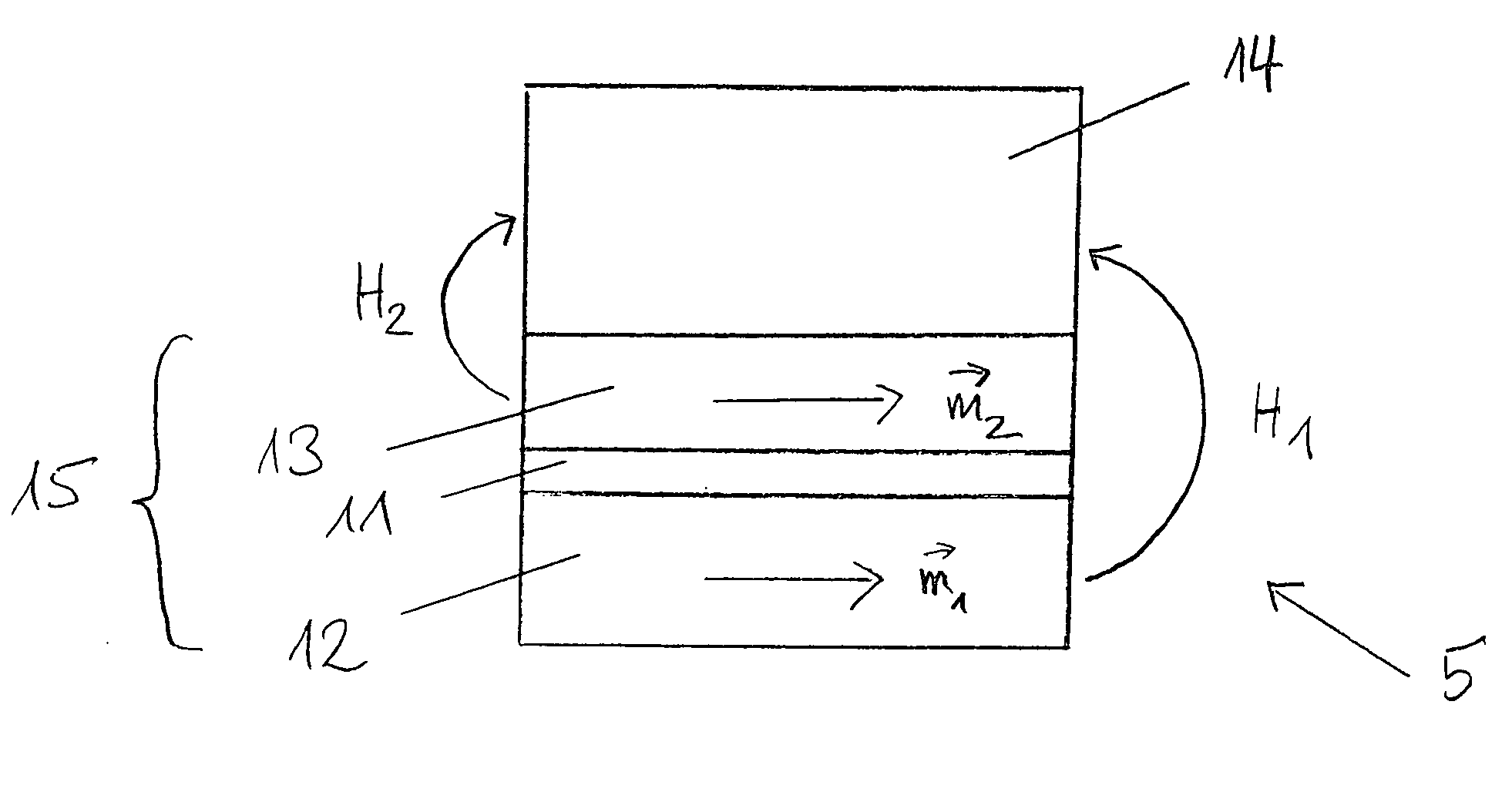
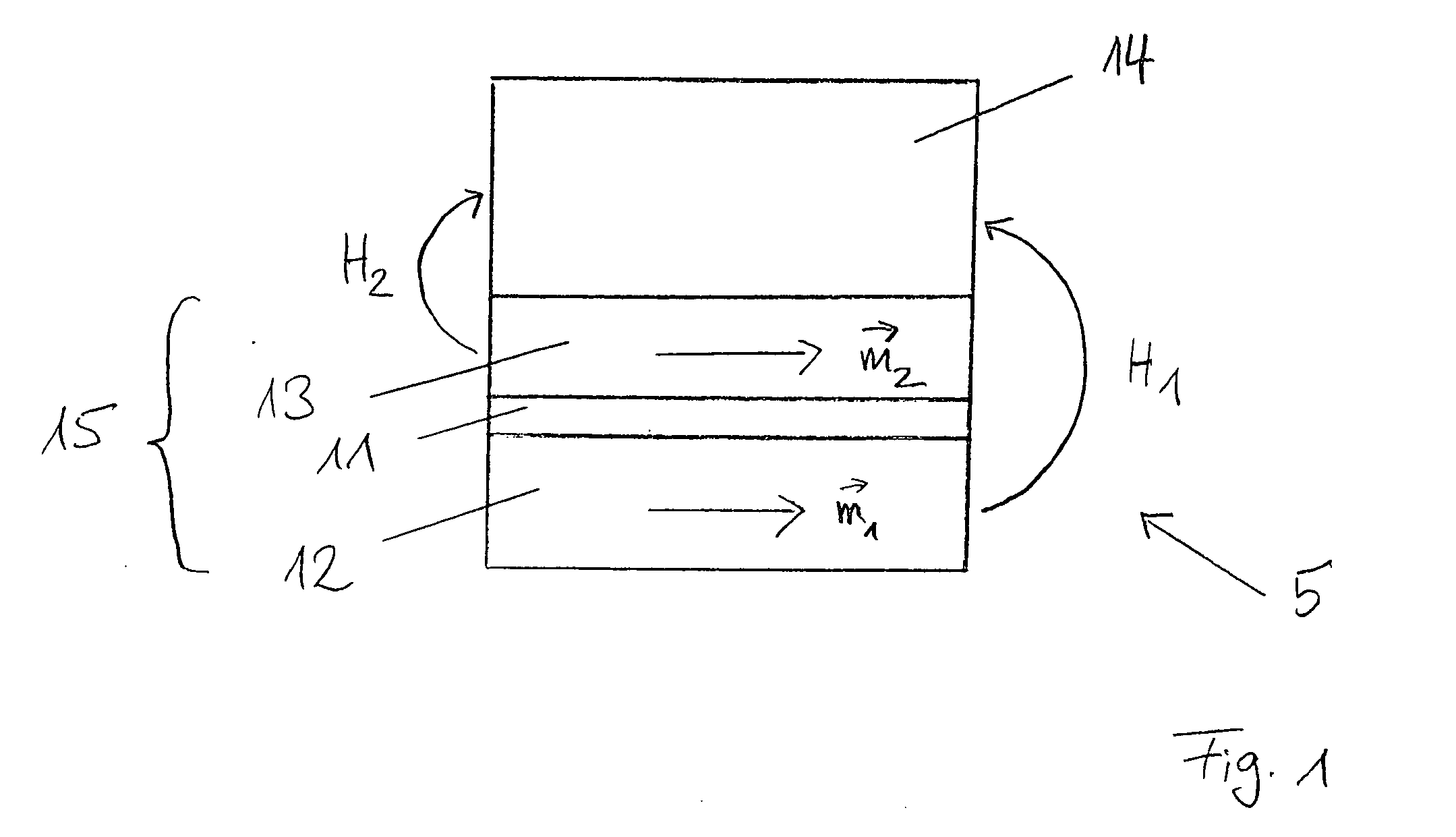
[0016]FIG. 1 shows a first magnetic layer 12 with a resulting magnetization m1, having the direction indicated in FIG. 1, on which an intermediate layer 11 is situated. A second magnetic layer 13 with a resulting magnetization mz having the direction indicated in FIG. 1 is arranged on intermediate layer 11. Positioned on second magnetic layer 13 is a magneto-resistive layer stack 14 as it is known per se from the related art. In particular, magneto-resistive layer stack 14 works on the basis of the GMR effect according to the coupled multilayer principle or according to the spin valve principle. First magnetic layer 12, intermediate layer 11 and second magnetic layer 13 jointly form a layer arrangement 15, which generates a resulting magnetic field that acts on the magneto-resistive layer stack. Furthermore, it is provided that first magnetic layer 12 and second magnetic layer 13 be ferromagnetically exchange-coupled via intermediate layer 11.

[0017] First magnetic layer 12 is, for ...


PUM


Abstract

A magneto-resistive layer system, in which a layer arrangement is provided in an environment of a magneto-resistive layer stack working on the basis of the GMR effect or the AMR effect, in particular the layer arrangement generating a resulting magnetic field that acts upon the magneto-resistive layer stack. The layer arrangement has a first magnetic layer and a second magnetic layer, which are separated from one another by a non-magnetic intermediate layer and are ferromagnetically exchange-coupled via the intermediate layer. Furthermore, a sensor element having such a layer system is provided, particularly for the detection of magnetic fields with respect to their strength and/or direction.

Description

BACKGROUND INFORMATION [0001] Magneto-resistive layer systems or corresponding sensor elements to be used in automobiles, for instance, in which the working point is able to be shifted by auxiliary magnetic fields, are known from the related art. Known, in particular, is the generation of such an auxiliary magnetic field by mounted macroscopic hard magnets or by current-traversed field coils. [0002] Besides that, in German Patent Application No. DE 101 28 135.8, a concept is discussed where, in the vicinity of a magneto-resistive layer stack, especially on or underneath the layer stack, a magnetically hard layer is deposited which couples into the actual sensitive layers of the layer stack, primarily because of its stray field. On the one hand, the highest possible coercivity is in the fore as target parameter and, on the other hand, the remanent magnetic field is in the fore as limiting parameter. However, in a vertical integration, such a magnetically hard layer also leads to an e...

Claims


Application Information

Patent Timeline
IPC IPC(8): G01R33/02G01R33/09
CPCB82Y25/00G01R33/093
Inventor RABE, MAIKSIEGLE, HENRIK
Owner ROBERT BOSCH GMBH
Why Eureka
Try Eureka