
Two dimensional quantization method for array beam scanning

Inactive Publication Date: 2006-06-08
RAYTHEON CO
View PDF3 Cites 5 Cited by
  • Summary
  • Abstract
  • Description
  • Claims
  • Application Information

AI Technical Summary

Benefits of technology

[0008] Some embodiments of the invention provide numerous technical advantages. A technical advantage of the present invention may include the capability to increase an effective phase resolution of an array antenna. Other technical advantages of the present invention may include the capability to reduce beam-steering errors in an array antenna; the capability to reduce quantization sidelobes in an array antenna; the capability to increase beam pointing performance in an array antenna while maintaining a repeatability of such performance; the capability to reduce complexity and / or costs of the phase shifters in an array antenna while increasing performance; and / or the capability to increase phase control of an array antenna, thereby increasing phase accuracy.
[0009] While specific advantages have been enumerated above, various embodiments may include all, some, or none of the enumerated advantages. Additionally, other technical advantages may become readily apparent to one of ordinary skill in the art after review of the following figures and description.

Problems solved by technology

A concern with such “stair step” approximations is that the stair stepping (e.g., jumping from one level to the next) can lead to significant errors in the desired scan angle of the signal beam.
Such a proportional randomization algorithm, however, is not repeatable.
This non-repeatable characteristic complicates checkout and testing of an antenna array.

Method used


Image

  • Two dimensional quantization method for array beam scanning
  • Two dimensional quantization method for array beam scanning
  • Two dimensional quantization method for array beam scanning

Examples


Embodiment Construction

[0020] It should be understood at the outset that although example implementations of embodiments of the invention are illustrated below, the present invention may be implemented using any number of techniques, whether currently known or in existence. The present invention should in no way be limited to the example implementations, drawings, and techniques illustrated below. Additionally, the drawings are not necessarily drawn to scale.

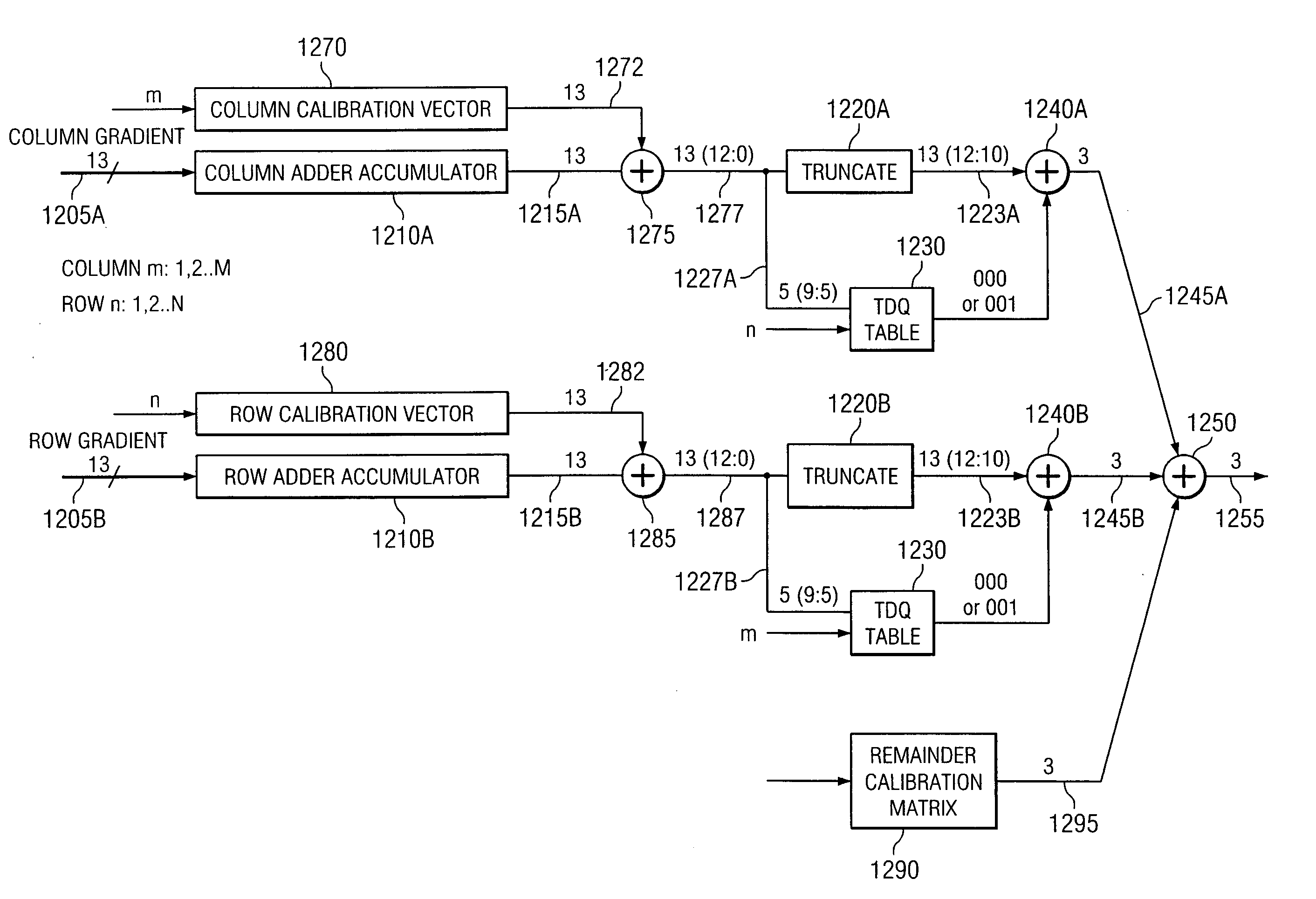
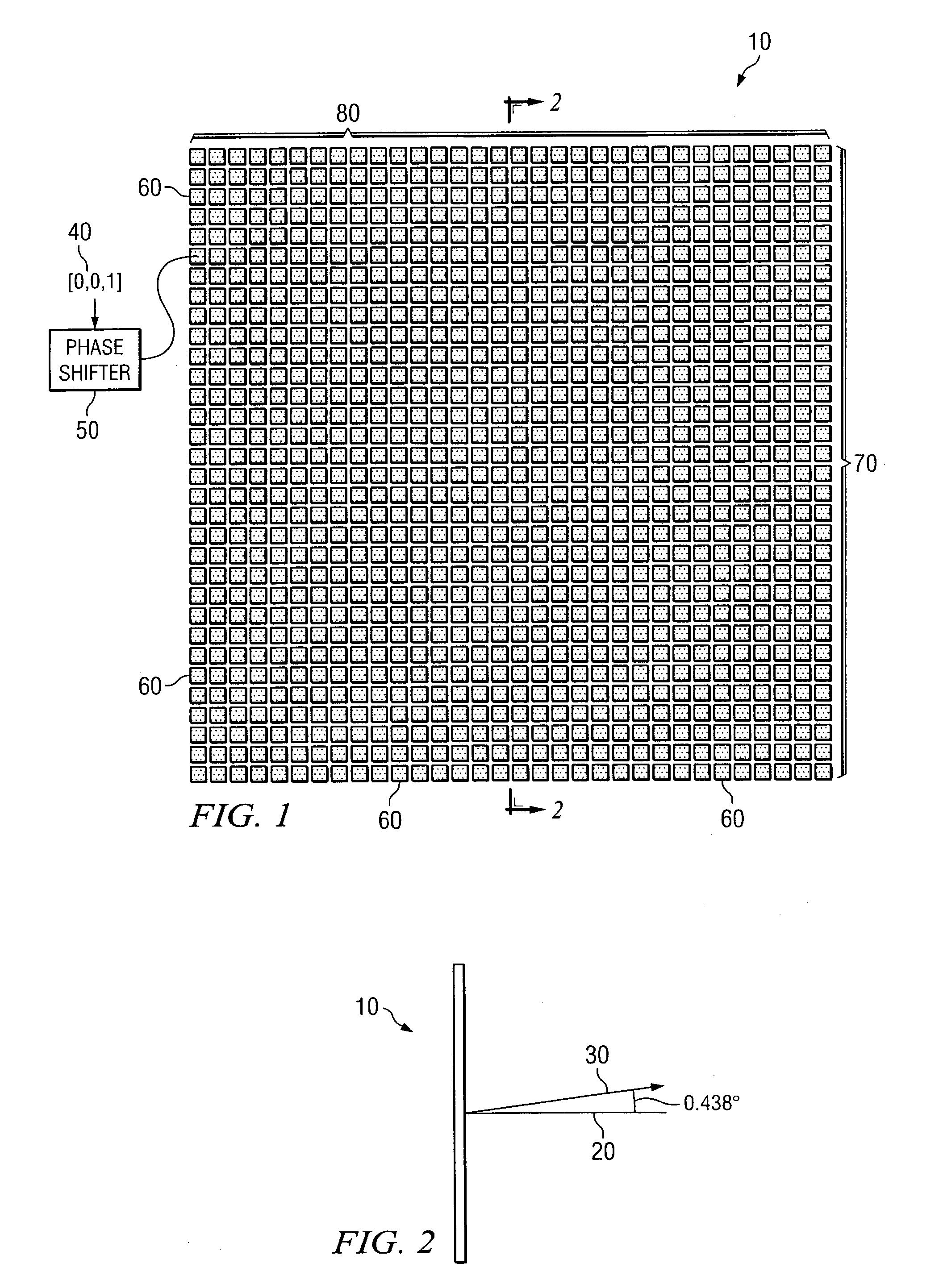
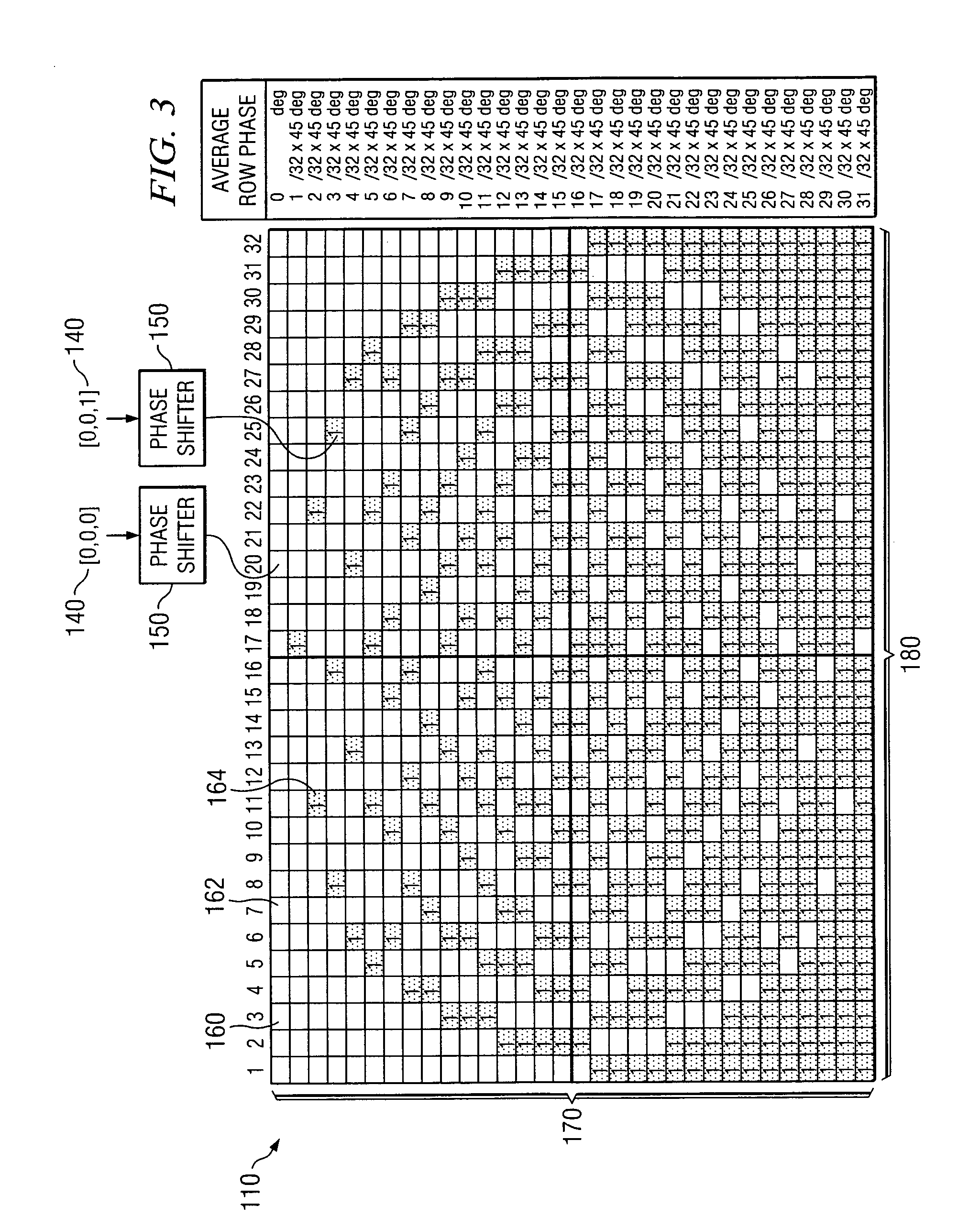
[0021]FIG. 1 is a schematic, top view drawing showing an illustrative example of an antenna array 10. The antenna array 10 of FIG. 1 includes a plurality of elements 60 that are arranged into rows 70 and columns 80. Each of the elements 60 in the antenna array 10 is generally operable to generate a radiated signal. Phase shifters 50 (only one shown in FIG. 1 for purposes of brevity) can be utilized to manipulate the phases of the radiated signals of the elements 60. An antenna array 10, having elements 60 that are radiating signals with different pha...


PUM


Abstract

According to one embodiment of the invention, a method of increasing a phase resolution of an array antenna, comprises providing an array antenna having a plurality of rows of antenna elements, each antenna element having a first phase resolution; for at least one row of the array antenna, positioning each of the antenna elements to one of first and second phases, the first and second phases separated by at least the first phase resolution; for the at least one row of the array antenna, a number of antenna elements positioned to the first phase is the product of a number of antenna elements in the at least one row of the array antenna and a desired row phase angle divided by the first phase resolution; and for the at least one row of the array antenna, a number of antenna elements positioned to the second phase is the number of elements in the at least one row of the array antenna minus the number of antenna elements in the at least one row positioned to the first phase.

Description

GOVERNMENT FUNDING [0001] The U.S. Government may have certain rights in this invention as provided for in the terms of Contract No. N68936-03-C-0038 issued by the Naval Air Warfare Center, Weapons Division (NAWCWD) as part of a Defense Advanced Research Project Agency (DARPA) project.TECHNICAL FIELD OF THE INVENTION [0002] The present invention relates generally to array antennas, and more particularly, but not by way of limitation, to a two-dimensional quantization method for array beam scanning. BACKGROUND OF THE INVENTION [0003] Binary digital phase shifters with phase increments of 360° / 2n (referred to as “n-bit phase shifters”) are commonly used to scan a signal beam of a phased antenna array. Such digital phase shifters typically produce a “stair step” approximation to a desired linear phase gradient. A concern with such “stair step” approximations is that the stair stepping (e.g., jumping from one level to the next) can lead to significant errors in the desired scan angle of...

Claims


Application Information

Patent Timeline
IPC IPC(8): H01Q3/26
CPCH01Q3/38H01Q3/385
Inventor HEMMI, CHRISTIAN O.MCCULLOUGH, MARC H.BALL, BRIAN L.
Owner RAYTHEON CO
Learn More