Display device incorporating a phase-change layer

Inactive Publication Date: 2006-06-08
HON HAI PRECISION IND CO LTD
View PDF10 Cites 10 Cited by
  • Summary
  • Abstract
  • Description
  • Claims
  • Application Information

AI Technical Summary

Benefits of technology

[0016] Comparing with conventional LCD devices, the present display device has following advantages. The natural light emitted from the light source in the conventional LCD device with polarizer needs to be transformed into P-polarized light or S-polarized light, and only one of the P-polarized light and S-polarized light can be utilized for display. The present display device utilizes a phase-change material to serve as a light switch and c

Problems solved by technology

However, in the transmissive LCD device, the backlight module consumes 50% or more of the total power consumed by the LCD device.
That is, the backlight module is a major contributor to power consumption.
In addition, because a polarizer is a typically necessary element in the LCD device and only polarized light can pass the polarizer, about 50% or more of the light emitted from the backlight module 10 still cannot be utilized.
However, using the reflection of ambient light is disadvantageous, because the visibility of the liquid crystal panel is extremely low when the surroundin

Method used


Image

  • Display device incorporating a phase-change layer
  • Display device incorporating a phase-change layer
  • Display device incorporating a phase-change layer

Examples


Example

[0023] Reference will now be made to the drawings to describe preferred embodiment of the present display device, in detail.

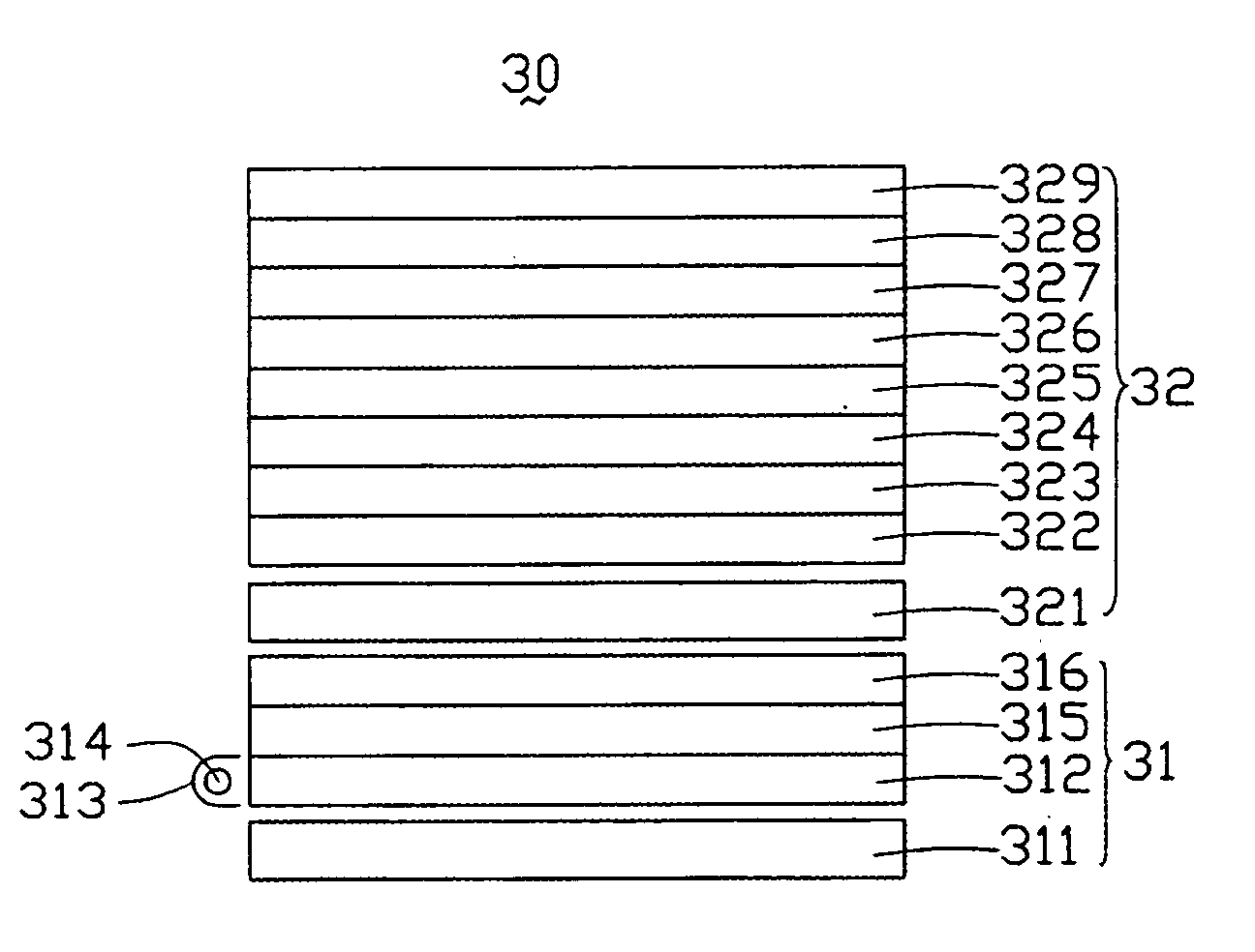
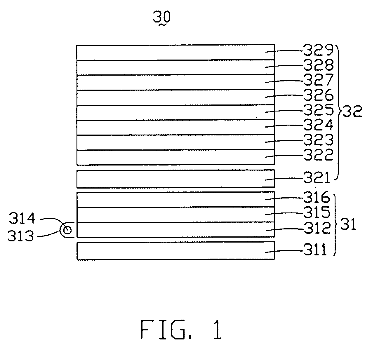
[0024] Referring to FIG. 1, a display device 30, in accordance with a preferred embodiment, is shown. The display device 30 includes a backlight module 31 and a display panel 32. The backlight module 31 is placed under the display panel 32 and provides the light to illuminate the display panel 32, as needed.

[0025] The backlight module 31 includes a light source 314, a light source cover 313, an LGP 312, a reflective sheet 311, a diffusing sheet 315, and a light condenser 316. The light source 314 is placed at one side, i.e., an incidence surface of the LGP 312. The light source 314 is generally, e.g., a light emitting diode (LED) or a cold cathode fluorescence lamp (CCFL). The light source cover 313 partly surrounds the light source 314. The reflective sheet 311, the LGP 312, the diffusing sheet 315 and the light condenser 316 are arranged in that order. The ...


PUM


Abstract

A display device (30) includes a display panel (32) and a backlight module (31). The display panel includes a transparent anode layer (325), a transparent cathode layer (323), and a layer of phase-change material (324) sandwiched therebetween. The backlight module is arranged adjacent the display panel. The display device utilizes a phase-change material to serve as a light switch and can fully make use of the available light emitted from the backlight module for display purposes, thereby permitting a high utilization efficiency of light to be realized. In addition, the function of a light switch is achieved by the electron transition occurring in the phase-change material. Because the time of such an electron transition is very short, the response time of the display panel is thus decreased.

Description

BACKGROUND OF THE INVENTION [0001] 1. Field of the Invention [0002] The present invention relates to a display device and, more particularly, to a flat panel display (FPD) device with high utilization efficiency of light. [0003] 2. Discussion of the Related Art [0004] In order to display words and / or images, a display device is generally used. Up to now, various display devices, such as cathode-ray tube (CRT) displays, FPDs, etc., have been developed. Specially, liquid crystal display (LCD) devices, as one kind of a FPD, have been used in a variety of fields due to their compact size and low power consumption. [0005] Unlike the CRT display, a liquid crystal panel of an LCD device does not itself emit light. Instead, in a conventional transmissive LCD device, an illuminator, i.e. a backlight module, is provided at a rear side of the LCD device. The liquid crystal of the liquid crystal panel of the LCD device typically functions as a light switch. Specifically, the liquid crystal cont...

Claims


Application Information

Patent Timeline
IPC IPC(8): G02F1/1335
CPCG02F1/15
Inventor CHEN, GA-LANE
Owner HON HAI PRECISION IND CO LTD
Why Eureka
Try Eureka