Fluid treatment system and radiation source module for use therein

a radiation source module and treatment system technology, applied in the field of fluid treatment system and radiation source module for use therein, can solve the problems of not providing the cost effective range of services and/or radio resource efficiency that will be desired for will systems providing voice and data services, and frankel does not teach the management of data transmission and/or network resources between multiple subscriber units

Inactive Publication Date: 2006-06-08
WI LAN INC
View PDF7 Cites 13 Cited by
  • Summary
  • Abstract
  • Description
  • Claims
  • Application Information

AI Technical Summary

Benefits of technology

[0008] It is an object of the present invention to provide a novel system, apparatus and method of providing local loop services and the like via wireless communication which obviates or mitigates at least some of the above-identified disadvantages of the prior art.

Problems solved by technology

The present inventors have determined however, that while WLL systems based upon mobile cellular technologies can provide reasonable voice performance, they do not provide a cost effective range of services and / or radio resource efficiencies that will be desired for WILL systems which provide voice and data services.
While the remote data terminal taught by Frankel does deal with sharing the DSL line between multiple devices / users at the subscriber end, as the DSL line is not shared with other subscribers / remote terminals, Frankel does not teach the management of data transmission and / or network resources between multiple subscriber units.

Method used


Image

  • Fluid treatment system and radiation source module for use therein
  • Fluid treatment system and radiation source module for use therein
  • Fluid treatment system and radiation source module for use therein

Examples


Embodiment Construction

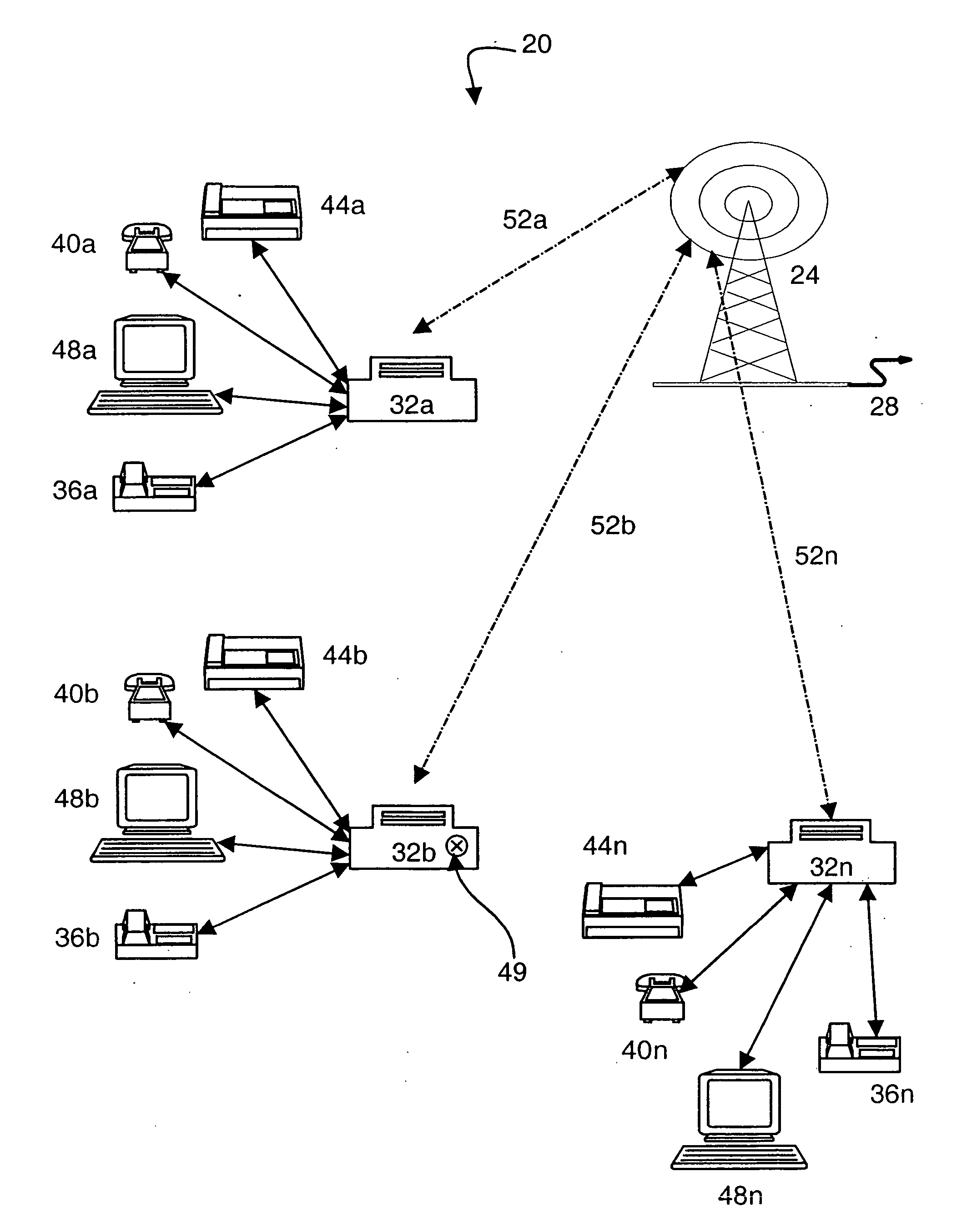
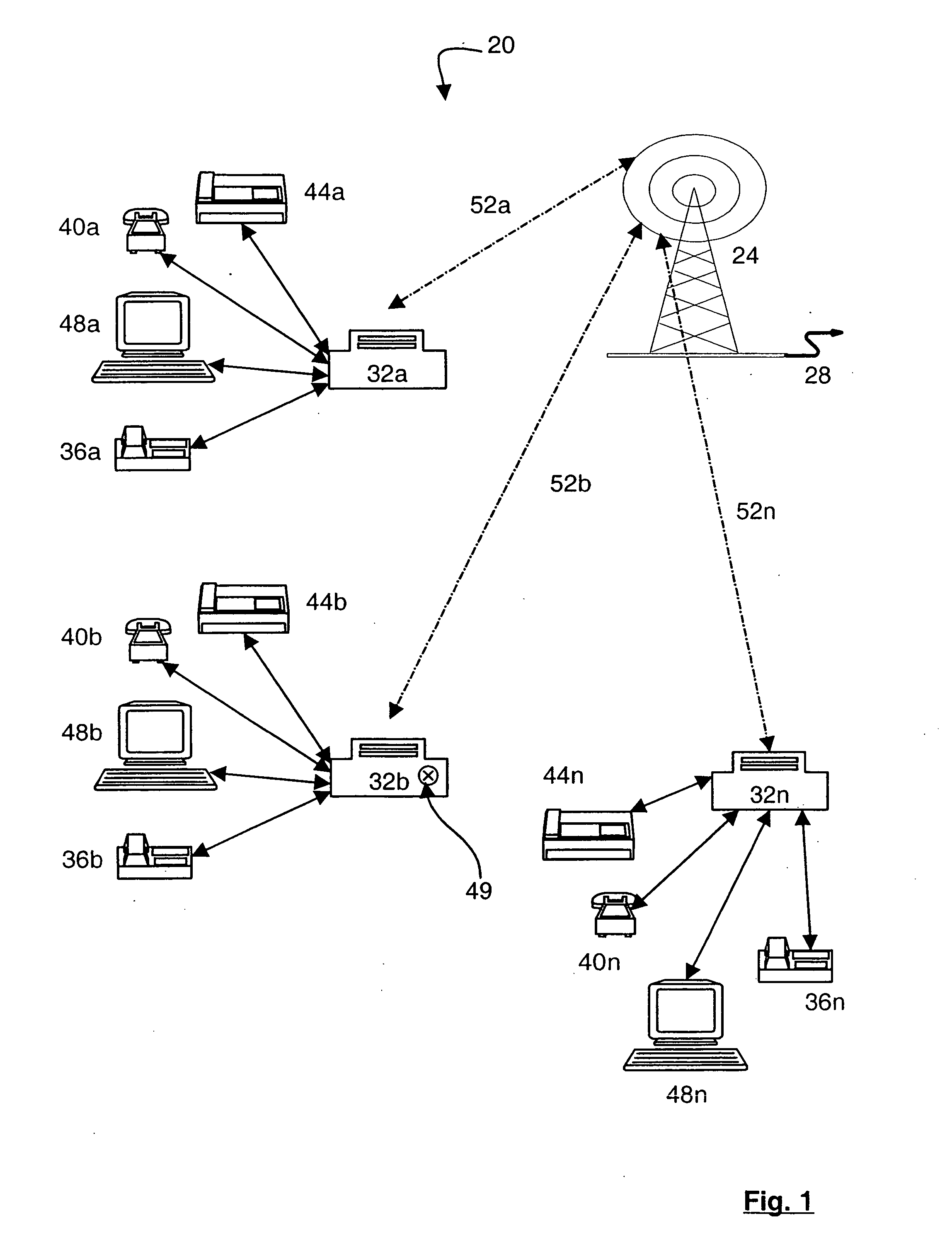
[0032] A wireless local loop (WLL) system in accordance with an embodiment of the present invention is indicated generally at 20 in FIG. 1. System 20 includes a radio base station 24 which is preferably connected to voice and / or data telecommunications network (not shown), such as a land line-based switched telephone network and / or data network, by one or more backhauls 28. A backhaul 28 can be a T1, T3, E1, E3, OC3 or other suitable land line link, or can be a satellite or other radio or microwave channel link or any other link suitable for operation as a backhaul as will occur to those of skill in the art.

[0033] Base station 24 communicates with a plurality of subscriber stations 32 which are installed at subscriber premises. Depending upon the amount of radio resources (spectrum, transmission power, etc.) available, the multiple access technique employed (FDMA, TDMA, CDMA, etc.) and / or the configuration and requirements of the subscriber stations 32, it is contemplated that ‘n’ ...


PUM


Abstract

A wireless local loop system manages radio data transmission capacity and network resources shared by a plurality of subscriber stations by considering the type of connections desired to be created to the subscriber stations and the radio data transmission capacity, and in some cases QoS parameters, and network resources required for those connections. The subscriber stations include data and telephony ports and can include a subscriber utilization client (SUC) to assist in the management process. The SUC in each subscriber station communicates with a network utilization manager (NUM) to request network resources from the base station. The NUM determines the requirements, in data transmission capacity and / or QoS levels, for the desired connection and considers the utilization of the network resources at the base station, or sector of the base station, in determining whether to establish the desired connection. The NUM can consider the required level and a desired level of data transmission capacity and / or QoS levels and allocate resources for the connection according to either level, or therebetween. The SUC and NUM can prioritize the establishment of connections on an appropriate basis, including the type of connection, the parties to the connection, the revenue potential of the connection and the port for the connection at the subscriber station, etc.

Description

FIELD OF THE INVENTION [0001] The present invention relates to a system, apparatus and method of providing local loop telecommunications services, or the like, through a wireless media. More specifically, the present invention relates to providing such services for both data and voice in a manner which can provide good usage of available shared radio resources, which can include spectrum / bandwidth and transmission power levels and network resources. BACKGROUND OF THE INVENTION [0002] Much interest has been expressed recently in providing local loop services via mediums other than public switched telephone network (PSTN) copper wire local loops. Local loop services, also referred to as ‘last mile’ services, are the connection between the subscriber location and a local office or other access point to the PSTN. [0003] One alternative to conventional copper wire local loop infrastructures is wireless local loop (WLL) systems that connect subscribers to the PSTN using radio signals to e...

Claims


Application Information

Patent Timeline
Patent Type & Authority Applications(United States)
IPC IPC(8): H04L12/26H04Q7/00H04L12/56H04M3/00H04W4/24H04W28/20H04W28/24H04W72/10H04W76/02H04W84/00H04W84/14H04W88/08H04W88/16
CPCH04L47/14H04L47/24H04W4/24H04W28/24H04W72/10H04W76/02H04W84/14H04W88/08H04W76/10H04W28/02H04W72/56H04W8/04
Inventor PATHAK, YATISHSTUMM, MICHAELSNELGROVE, WILLIAM M.
Owner WI LAN INC
Why Eureka
Try Eureka