
Multicarrier transmission apparatus and method

Inactive Publication Date: 2006-06-08
NEC CORP
View PDF13 Cites 6 Cited by
  • Summary
  • Abstract
  • Description
  • Claims
  • Application Information

AI Technical Summary

Benefits of technology

[0060] It is therefore an object of the present invention, which has been devised in consideration of the problem above, to provide a multicarrier transmission apparatus and a multicarrier transmission method capable of efficiently conducting multicarrier transmission even when non-periodic noise takes place.
[0082] In accordance with the present invention, even under non-periodic noise, multicarrier transmission can be efficiently conducted. Even when abrupt noise takes place, a large transmission rate and high transmission quality of a communication line can be secured.

Problems solved by technology

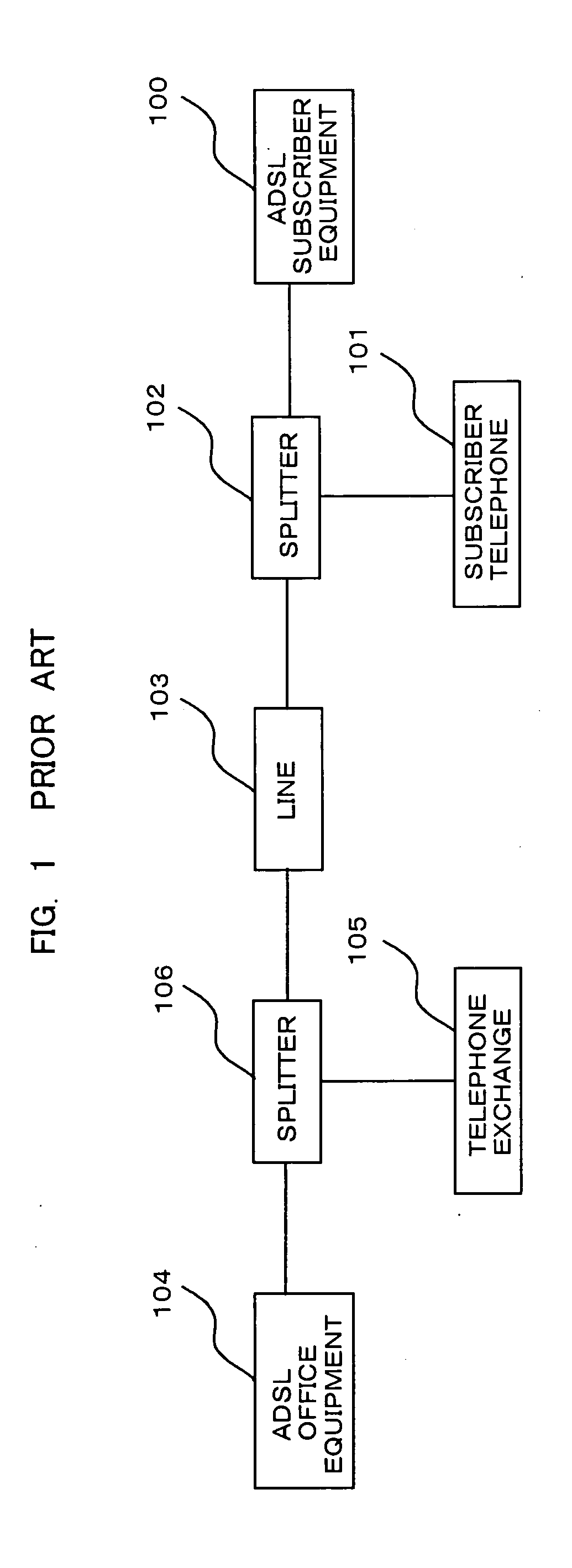
This possibly leads to a problem of occurrence of noise that lowers the data transmission rate on the line of the ADSL system.
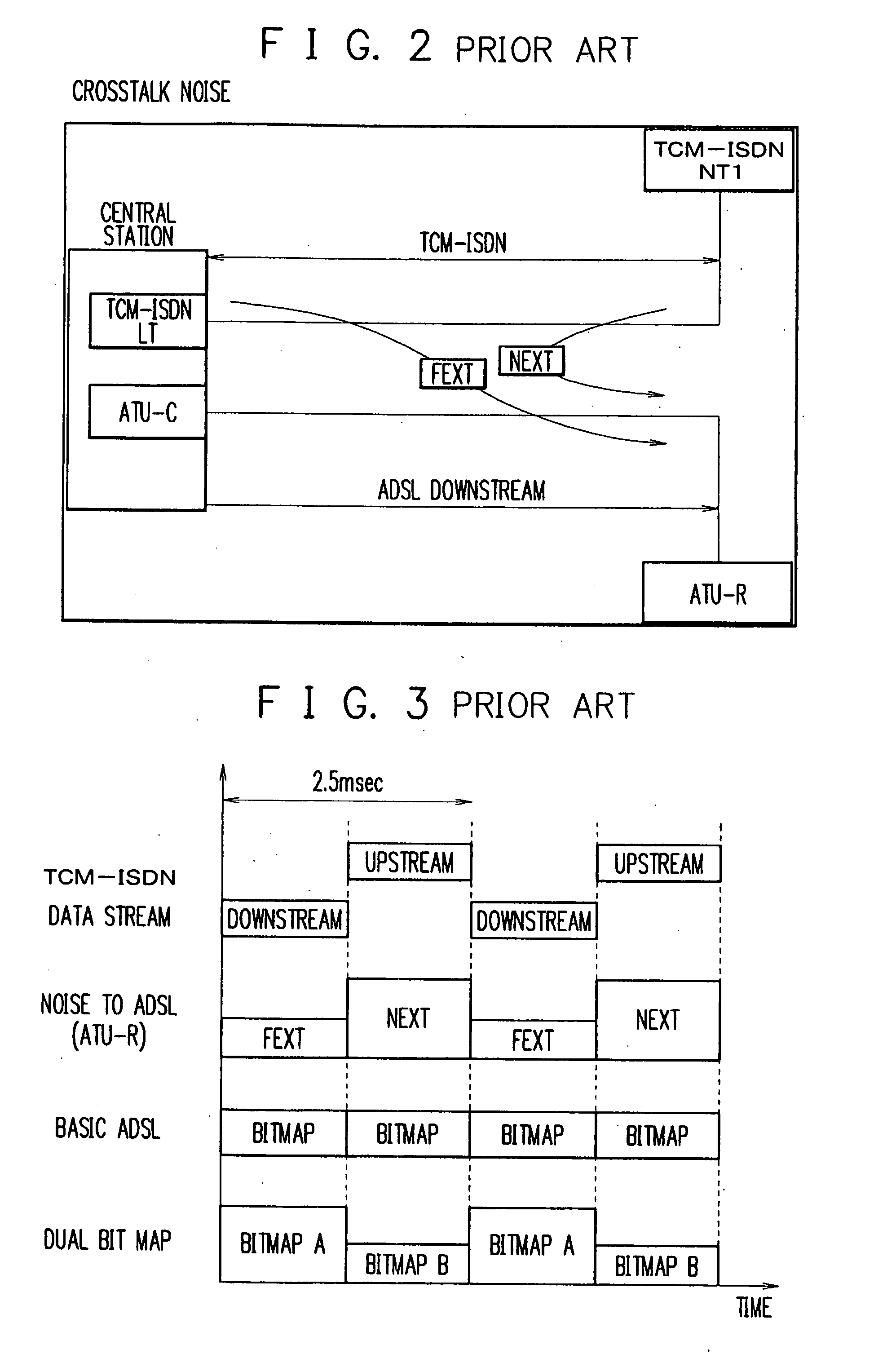
Among the influences from the ISDN line onto the line of the ADSL system, crosstalk noise from the ISDN line is most troublesome.
However, in the ADSL transmission system of this configuration, there arises another problem that the load imposed on the operator increases.
This disadvantageously causes a Near End Cross Talk (NEXT) in the ATU-R which is the terminal device of the ADSL system.
However, there exists a problem that noise like “burst” takes place for a short period of time during communication to resultantly cause disconnection of the line connection.
In the ADSL transmission system of the prior art, when such burst-like noise takes place for a short period of time during communication, it is not possible to predict a Power Spectrum Density (PSD) and a period of the noise.
The PSD cannot be fully measured during the ordinary initialization and training phase and hence the bit distribution ratios used for the data transmission are not appropriate.
Therefore, at occurrence of non-periodic noise, the multicarrier transmission cannot be efficiently conducted.

Method used


Image

  • Multicarrier transmission apparatus and method
  • Multicarrier transmission apparatus and method
  • Multicarrier transmission apparatus and method

Examples


first embodiment

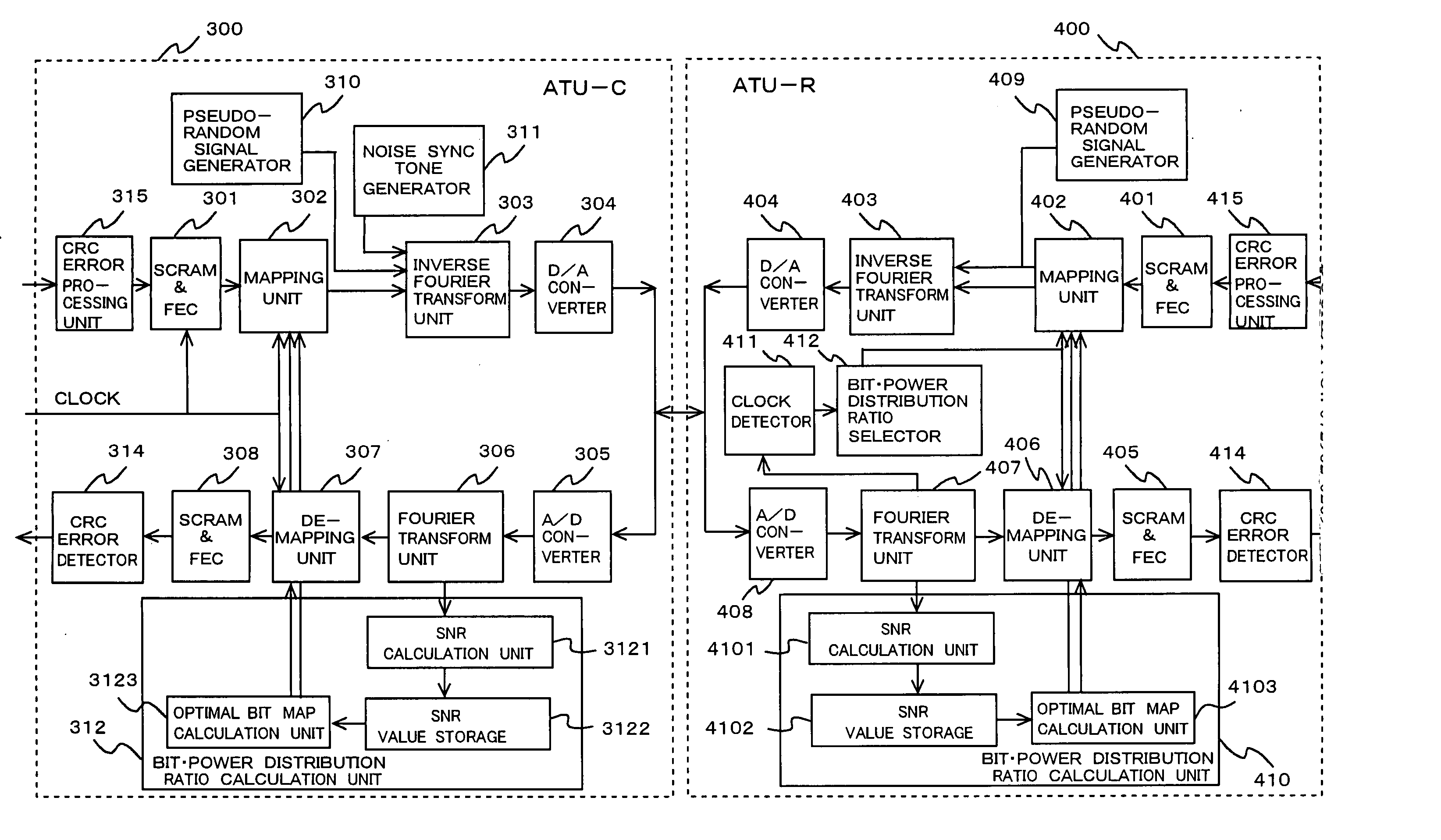
[0116] Referring now to FIG. 9, description will be given of a system configuration of a first embodiment of a multicarrier transmission system.

[0117] As can be seen from FIG. 9, in the embodiment of a multicarrier transmission system, a bit-power distribution ratio calculation module (312, 410) includes an SNR calculation module (3121, 4101), an SNR value storage (3122, 4102), and an optimal bit map calculation module (3123, 4103).

[0118] The SNR calculation module (3121, 4101) is a unit to calculate an SNR value of periodic noise. The SNR value storage (3122, 4102) is a unit to store the SNR value obtained by the SNR calculation module (3121, 4101). The optimal bit map calculation module (3123, 4103) calculates an optimal bit distribution ratio to be assigned to each carrier for data transmission according to the calculation results of SNR values stored in the storage (3122, 4102). Description will be given of operation for the SNR calculation module (3121, 4101) of the embodimen...

second embodiment

[0126] Description will be given of a second embodiment.

[0127] In the first embodiment of a multicarrier transmission system, the bit-power distribution ratio calculation module (312, 410) calculates the bit distribution ratios shown in FIGS. 15 to 17 according to the SNR value calculation results of FIG. 12 to 14 stored in the SNR value storage (3122, 4102). However, according to an aspect of the second embodiment of a multicarrier transmission system, the bit-power distribution ratio calculation module (312, 410) detects a minimum SNR value of each frequency according to the SNR value calculation results of FIGS. 12 to 14 stored in the storage (3122, 4102). On the basis of the minimum SNR value detected for each frequency, the system calculates an SNR value including the minimum SNR value of each frequency as SNR value calculation results obtained through plural calculations as shown in FIGS. 12 to 14. Referring now to FIGS. 9, 19, and 20, description will be given of the second ...

third embodiment

[0133] Description will now be given of a third embodiment.

[0134] The third embodiment has an aspect as below. Using the SNR calculation results attained through plural calculations and stored in the SNR storage 3122 in the first embodiment of a multicarrier transmission system, the third embodiment detects an SNR calculation result including a frequency zone of SNR values equal to or less than a predetermined SNR reference value and calculates an optimal bit map for data transmission as shown in FIG. 18 on the basis of the SNR calculation result thus detected. Referring now to FIGS. 9, 21, and 22, description will be given of the third embodiment of a multicarrier transmission system.

[0135] The SNR calculation unit 3121 calculates, as in the first embodiment, the SNR value of each carrier plural times by use of a transmission signal such as a sync symbol and stores calculation results of SNR values of A to E shown in FIG. 22 in the SNR value storage 3122 (step S21).

[0136] Using ...


PUM


Abstract

A bit-power distribution ratio calculation unit measures several times an SNR of periodic noise occurring on a communication line to calculate several times, according to the measurement results of the SNR thus measured, a bit distribution ratio to be assigned to each carrier for data transmission for each measurement result. The calculation unit compares the calculated bit distribution ratios with each other to detect a minimum bit value of each carrier to calculate, according to the detected minimum bit values of the respective carriers, a minimum bit distribution ratio including the minimum bit value of each carrier. The calculation unit delivers the minimum bit distribution ratio to a demapping unit and a mapping unit, which conduct data transmission using the minimum bit distribution ratio. Therefore, a multicarrier transmission device can efficiently conduct multicarrier transmission even at occurrence of non-periodic noise.

Description

BACKGROUND OF THE INVENTION [0001] 1. Field of the Invention [0002] The present invention relates to a multicarrier transmission apparatus and a multicarrier transmission method for use with an x Digital Subscriber Line (xDSL; x represents A, S, V, and the like) to conduct data transmission through a metallic cable such as a telephone line at a high transmission rate of several megabits per second, and in particular, to a multicarrier transmission apparatus and a multicarrier transmission method to conduct data transmission at a high transmission rate in an environment in which noise occurs abruptly. [0003] 2. Description of the Prior Art [0004] Recently, attention has been drawn to an xDSL technique capable of accomplishing data transmission at a high transmission rate of several megabits per second using a metallic cable such as a telephone line. Especially, an Asymmetric Digital Subscriber Line (ADSL) has collected attention. On the ADSL, a forward or upstream line and a reverse ...

Claims


Application Information

Patent Timeline
IPC IPC(8): H04B17/00H04B1/38H04K1/10
CPCH04L5/0007H04L5/0046H04L5/006H04W72/0453H04W72/542
Inventor OKAMURA, YUUSAKU
Owner NEC CORP
Learn More