Optical waveguide device, manufacturing method thereof, optical information processing apparatus, and electronic equipment

a technology of optical waveguides and manufacturing methods, applied in the direction of optical waveguide light guides, instruments, optics, etc., can solve the problems of rc signal delay, data exchange amount required between, occurrence of various high-frequency problems, etc., and achieve the effect of improving yield and easy and precise performan

Active Publication Date: 2006-06-08
SONY CORP
View PDF5 Cites 9 Cited by
  • Summary
  • Abstract
  • Description
  • Claims
  • Application Information

AI Technical Summary

Benefits of technology

[0016] It is accordingly an embodiment of the present invention to provide an optical waveguide device which can improve the yield and can easily and precisely perform the alignment of lens portions for obtaining effective incidence and emergence of light.

Problems solved by technology

However, a data exchange amount required between the chips has remarkably increased with a recent higher functionality of MPU, resulting in the occurrence of various high-frequency problems.
Such high-frequency problems typically include RC signal delay, impedance mismatch, EMC / EMI, and crosstalk.
However, the effects by the optimization of wiring and placement and the development of new materials have been blocked by physical limitations in recent years.
However, there arise other problems such as increased heating value due to the multilayering and thermal stress between the semiconductor chips.
As a result, there is a possibility of reduction in alignment accuracy and yield.

Method used


Image

  • Optical waveguide device, manufacturing method thereof, optical information processing apparatus, and electronic equipment
  • Optical waveguide device, manufacturing method thereof, optical information processing apparatus, and electronic equipment
  • Optical waveguide device, manufacturing method thereof, optical information processing apparatus, and electronic equipment

Examples


first preferred embodiment

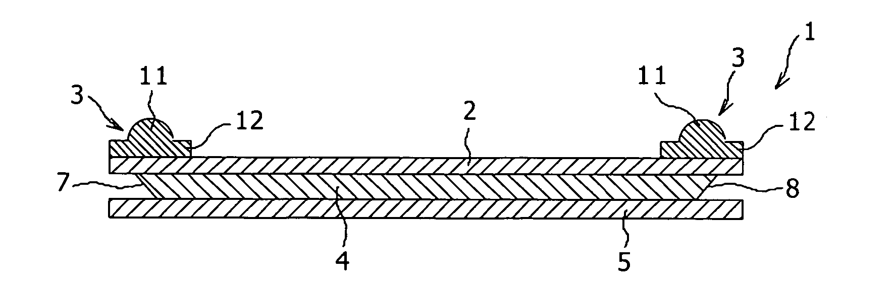
[0075]FIG. 1A is a schematic sectional view of an optical waveguide device 1 according to the present invention, and FIG. 1B is an exploded view of FIG. 1A.

[0076] As shown in FIGS. 1A and 1B, the optical waveguide device 1 has a laminated structure composed of a first cladding 2, a second cladding 5 independent of the first cladding 2, and a core 4 sandwiched between the first and second claddings 2 and 5, wherein light is guided in the core 4. The core 4 serves to guide an incident optical signal, and the claddings 2 and 5 serve to confine the optical signal in the core 4. The core 4 is formed of a material having a high refractive index, and the claddings 2 and 5 are formed of a material having a refractive index lower than that of the core 4.

[0077] The cladding 2 is formed from a flexible sheet, and a pair of light collimating or a focusing section 3 are bonded to the upper surface of the cladding 2 at its opposite ends corresponding to light incident and emergent portions 7 an...

second preferred embodiment

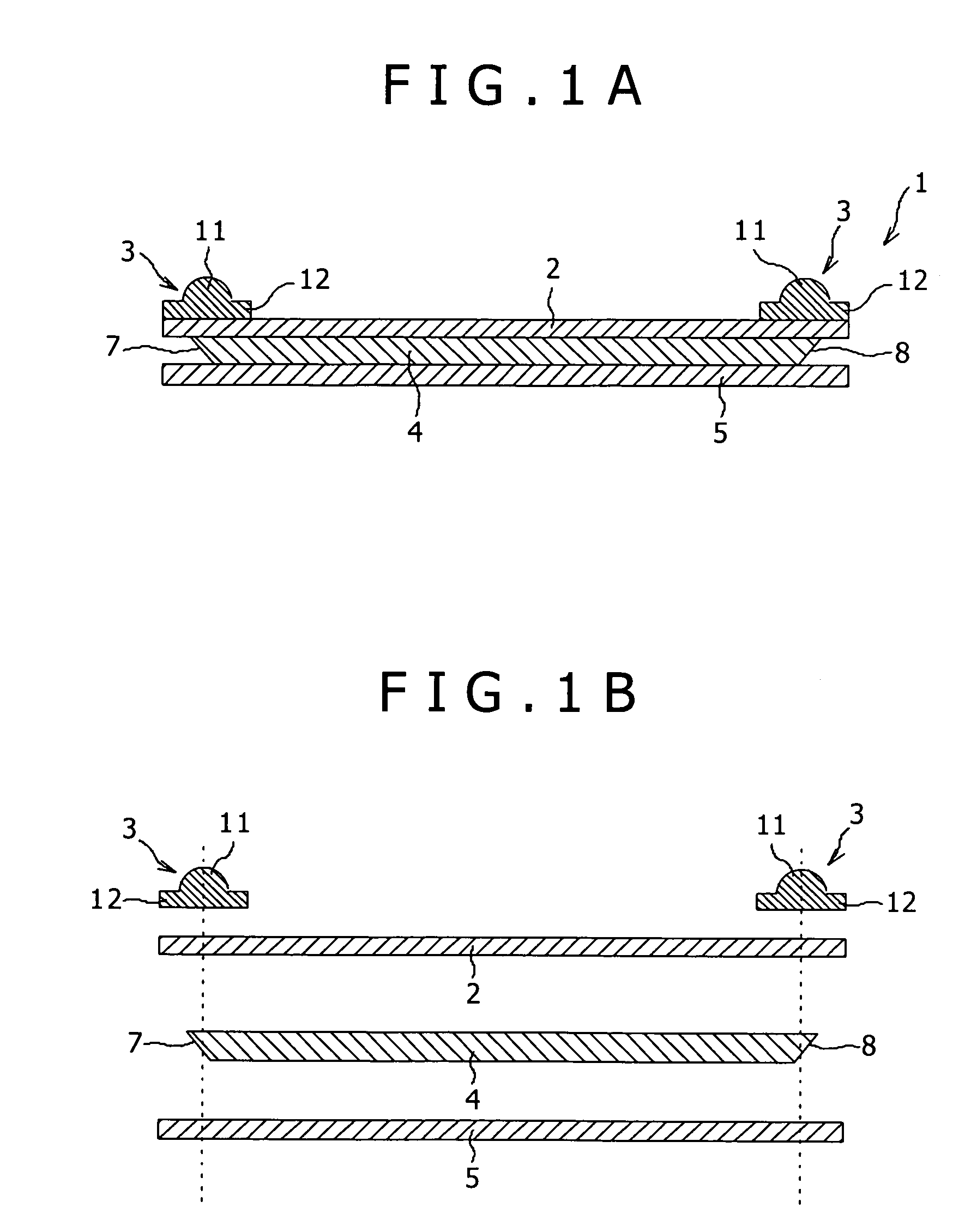
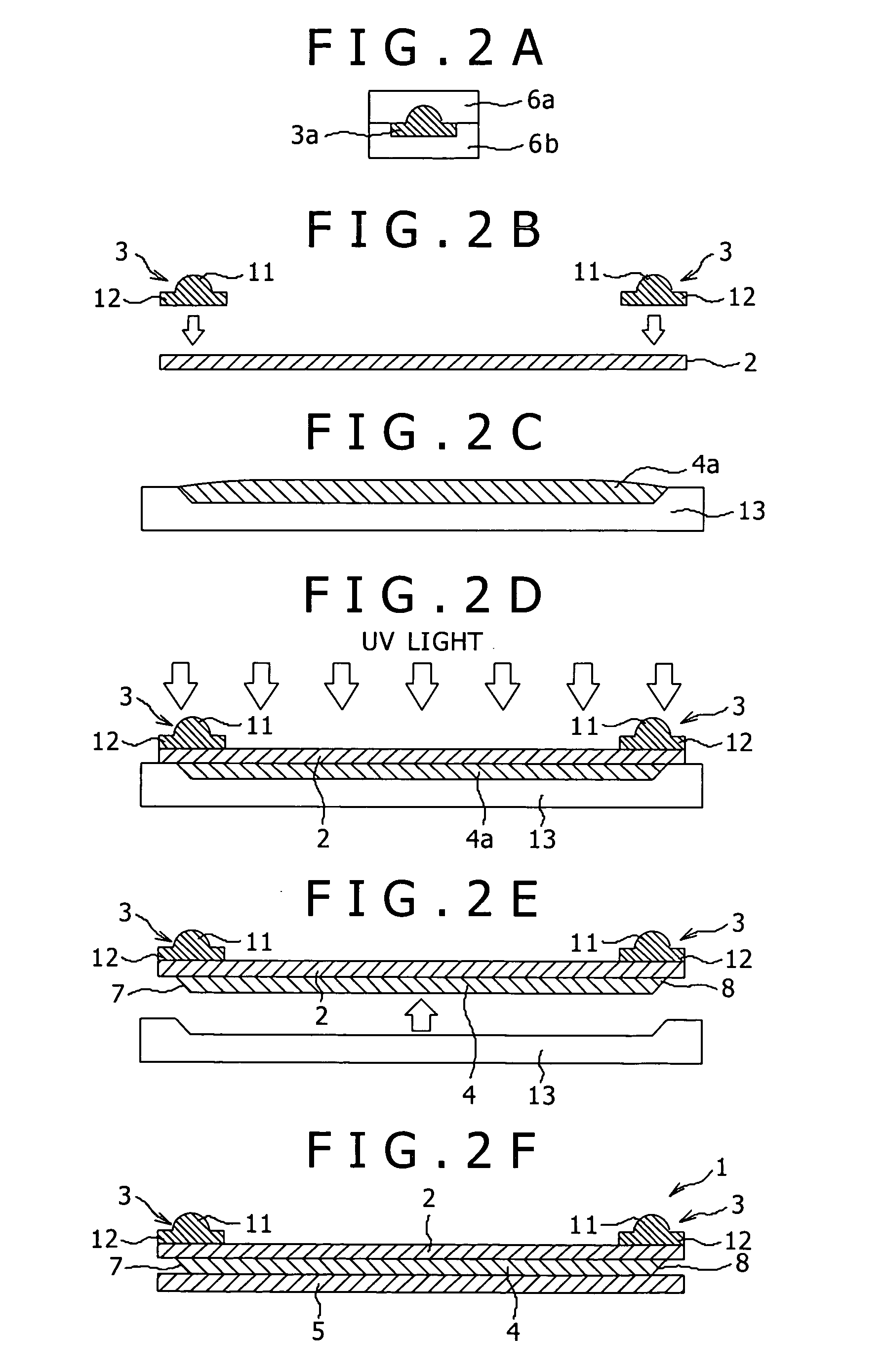
[0094]FIGS. 3A to 3E are schematic sectional views showing another manufacturing method for the optical waveguide device 1.

[0095] As shown in FIG. 3A, a core material 4a is filled into a mold 13. As shown in FIG. 3B, the first cladding 2 formed from a flexible sheet is attached to the upper surface of the mold 13 with the core material 4a interposed between the cladding 2 and the mold 13, and UV light is next applied to thereby cure the core material 4a. As shown in FIG. 3C, the mold 13 is removed to obtain a laminated structure composed of the cladding 2 and the core 4.

[0096] As shown in FIG. 3D, the pair of light collimating or a focusing section 3 (each formed as an integral member composed of the lens portion 11 and the lens supporting portion 12) previously fabricated by injection molding as similar to the step of FIG. 2A are bonded to the upper surface of the cladding 2 opposite to the lower surface thereof where the core 4 is bonded, at the opposite ends corresponding to th...

third preferred embodiment

[0099]FIGS. 4A to 4C show an optical information processing apparatus 14 according to the present invention which includes an optical waveguide device 1 according to the present invention, a plurality of light emitting devices (e.g., lasers) 9 for respectively launching light into a plurality of cores 4 of the optical waveguide device 1, and a plurality of light receiving devices (e.g., photodetectors) 10 for respectively receiving emergent light from the plural cores 4. More specifically, FIG. 4A is a schematic sectional view of the optical information processing apparatus 14, FIG. 4B is a bottom plan view of the optical waveguide device 1 shown in FIG. 4A with the second cladding 5 removed, and FIG. 4C is a top plan view of the optical waveguide device 1 shown in FIG. 4A.

[0100] As shown in FIG. 4B, the plural cores 4 are arranged in parallel with a given pitch on the cladding 2, and each core 4 has a pair of light incident and emergent portions 7 and 8 each formed as a 45° mirror...


PUM


Abstract

Disclosed herein is an optical waveguide device including a cladding having first and second surfaces opposite to each other, a core laminated to the first surface of the cladding for guiding light in a longitudinal direction thereof, the core having a pair of light incident and emergent portions at the opposite ends, and a pair of light collimating or focusing members bonded to the second surface of the cladding at the opposite ends corresponding to the light incident and emergent portions of the core.

Description

CROSS REFERENCES TO RELATED APPLICATIONS [0001] The present invention contains subject matter related to Japanese Patent Application JP 2004-352678 filed in the Japanese Patent Office on Dec. 6, 2004, the entire contents of which being incorporated herein by reference. BACKGROUND OF THE INVENTION [0002] The present invention relates to an optical waveguide device suitable for a light source module, optical interconnection, optical communication, etc., and also to a manufacturing method for the optical waveguide device, an optical information processing device using the optical waveguide device, and electronic equipment using the optical information processing apparatus. [0003] At present, signal transmission between semiconductor chips such as LSIs (large-scale integrated circuits) is generally made by electrical signals through board wiring. However, a data exchange amount required between the chips has remarkably increased with a recent higher functionality of MPU, resulting in th...

Claims


Application Information

Patent Timeline
Patent Type & Authority Applications(United States)
IPC IPC(8): G02B6/32G02B6/26G02B6/42
CPCG02B6/43
Inventor OHTORII, HIIZU
Owner SONY CORP
Why Eureka
Try Eureka