Diffractive optical element and method of manufacture

a technology manufacturing methods, applied in the field of diffractive optical elements, can solve problems such as being particularly sensitive to vibration and air currents

Inactive Publication Date: 2006-06-08
WAVEFRONT TECH INC
View PDF40 Cites 104 Cited by
  • Summary
  • Abstract
  • Description
  • Claims
  • Application Information

AI Technical Summary

Problems solved by technology

Recording of volume holograms conventionally involves exposing a photosensitive material to a laser beam; such arrangements, however, are particularly sensitive to vibration and air currents as well as fluctuations in temperature.

Method used


Image

  • Diffractive optical element and method of manufacture
  • Diffractive optical element and method of manufacture
  • Diffractive optical element and method of manufacture

Examples


Embodiment Construction

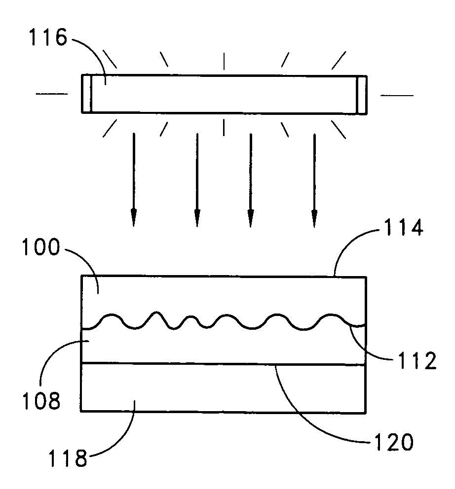
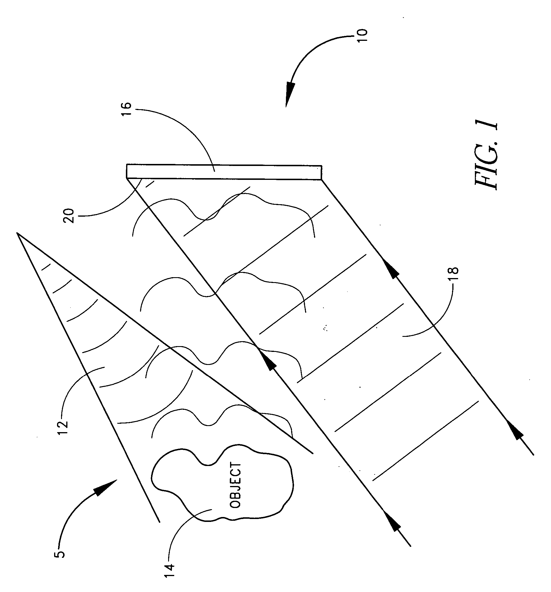
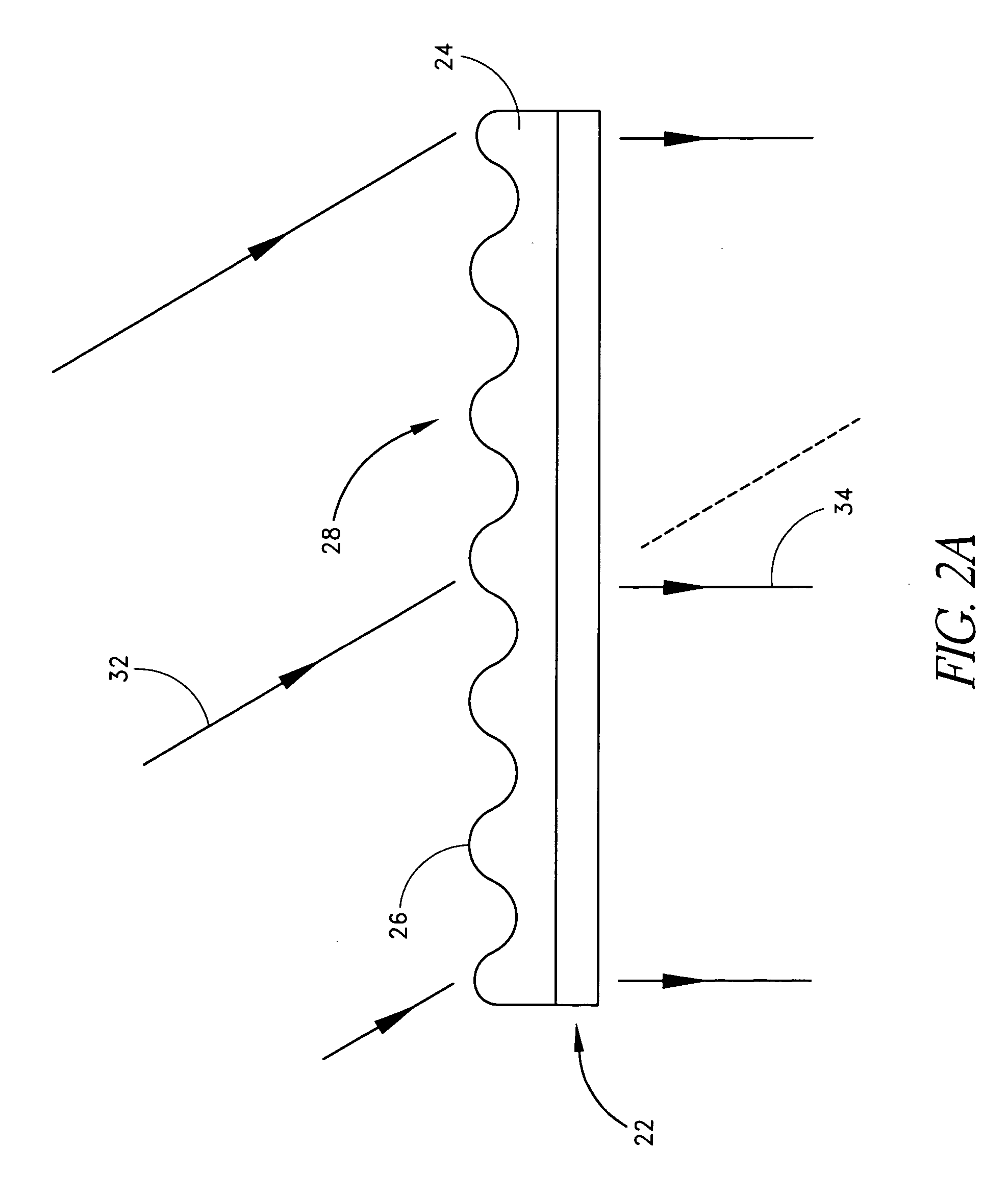
[0030] This application relates to diffractive optical elements, components comprising diffractive features that are arranged so as to diffract an incident light beam transforming it into a desired predetermined image and / or beam shape. Examples of such diffractive optical elements include structures having at least partially randomly distributed diffractive features such as diffusers as well as structures having diffractive features at least partially arranged in a periodic fashion such as, for example, diffraction gratings, holograms, and holographic optical elements (HOEs). Computer generated holograms (CGHs) as well as lithographically rendered diffractive optical elements are among the various types of diffractive optical elements. These examples, however, are not to be construed as limiting. For example, descriptions of holograms and methods of their manufacture set forth below may pertain also to other types of diffractive optical elements, including, for example, diffraction...


PUM


Abstract

A diffractive optical element such as a diffuser, diffraction grating, and / or hologram, can be manufactured by using a surface relief pattern on a surface of a surface relief tool. A layer of curable material is physically contacted with the surface relief pattern on the surface of the surface relief tool to thereby imprint the pattern on a surface of the layer. Diffractive features are formed in the layer by propagating energy through the surface relief tool and into the layer such that refractive index variations corresponding to the pattern are created in the layer. The resultant product is a diffractive optical element comprising a layer of material having diffractive features formed by a predetermined pattern of refractive index variations. The diffractive features originate at an undulating boundary and extend only from one side of the boundary into the material. The undulating boundary has an undulating pattern that corresponds to the predetermined pattern of refractive index variations.

Description

PRIORITY INFORMATION [0001] This application is a divisional application of U.S. patent application Ser. No. 10 / 036,198 (Attorney Docket WVFRNT.001A), filed Dec. 28, 2001, the entire contents of which are hereby incorporated by reference herein.BACKGROUND OF THE INVENTION [0002] 1. Field of the Invention [0003] This application relates to a method of forming diffractive features in a layer of material and more particularly to the formation of diffractive optical elements (DOEs), such as for example diffraction gratings, diffusers, volume holograms, and holographic optical elements, which employ such diffractive features. [0004] 2. Description of the Related Art [0005] In recent years, applications for diffractive optical elements and holograms has increased. DOEs and holograms are used for decoration and signs, as illustrations in publications such as magazines, to provide protection against tampering or counterfeiting as well as for beam shaping; the later being the function of hol...

Claims


Application Information

Patent Timeline
Patent Type & Authority Applications(United States)
IPC IPC(8): G03H1/02B29C35/08B29C59/02B29C59/04
CPCB29C35/0888B29C59/022B29C59/046B29C2035/0827B29C2059/023G03H1/0244G03H1/202G03H2001/0284G03H2001/2615G03H1/0276G03H2001/2635
Inventor RICH, CHRISPETERSEN, JOEL
Owner WAVEFRONT TECH INC
Why Eureka
Try Eureka