
Threat fire simulation system

a simulation system and fire simulation technology, applied in the field of simulation systems for use of force training, can solve the problems of inconvenient installation, trainee wear of safety eye gear, adverse effect of safety eye gear on the shooting accuracy of trainees, etc., and achieve the effect of easy integration, cost-effective manufacturing and minimal adjustmen

Inactive Publication Date: 2006-06-08
VIRTRA INC
View PDF9 Cites 3 Cited by
  • Summary
  • Abstract
  • Description
  • Claims
  • Application Information

AI Technical Summary

Benefits of technology

"The present invention provides a system for simulating a projectile impacting a user. The system includes an electrical impulse element that delivers a non-disabling electrical pulse to the user, simulating the impact of the projectile. The user can detect the simulated impact clearly. The system is cost-effective, readily incorporated into a simulation system, and requires minimal adjustment by an instructor during a training exercise."

Problems solved by technology

Additionally, training involves the development of decision-making skills in situations that are stressful and potentially dangerous.
Indeed, perhaps the greatest challenges faced by a trainee are when to use force and how much force to use.
If an officer is unprepared to make rapid decisions under the various threats he or she faces, injury to the officer or citizens may result.
One problem encountered with the shoot-back cannon is that due to the presence of high velocity nylon ball projectiles, the trainee must wear safety eye gear.
The safety eye gear can have an adverse effect on the shooting accuracy of the trainee.
Moreover, others in the area of the shoot-back cannon must also wear safety eye gear, generating both additional responsibility and liability for the training facility.
Even with safety eye gear on, there is still the potential that the nylon ball projectile could injure the trainee or others, or damage equipment in the area.
In addition, the nylon balls are a slipping hazard when on the floor because they can behave like ball-bearings under the foot of an individual.
In addition to problems associated with safety, the shoot-back cannon could misfire or miss the intended target.
When this happens, the training opportunity is lost.
More critically, however, the trainee may consciously or subconsciously marginalize real-world threats.
Consequently, time intensive collection of the nylon balls is required.
Finally, the shoot-back cannon is a mechanical device prone to break-down and wear-and-tear over time, necessitating costly repair and / or replacement.

Method used


Image

  • Threat fire simulation system
  • Threat fire simulation system
  • Threat fire simulation system

Examples


Embodiment Construction

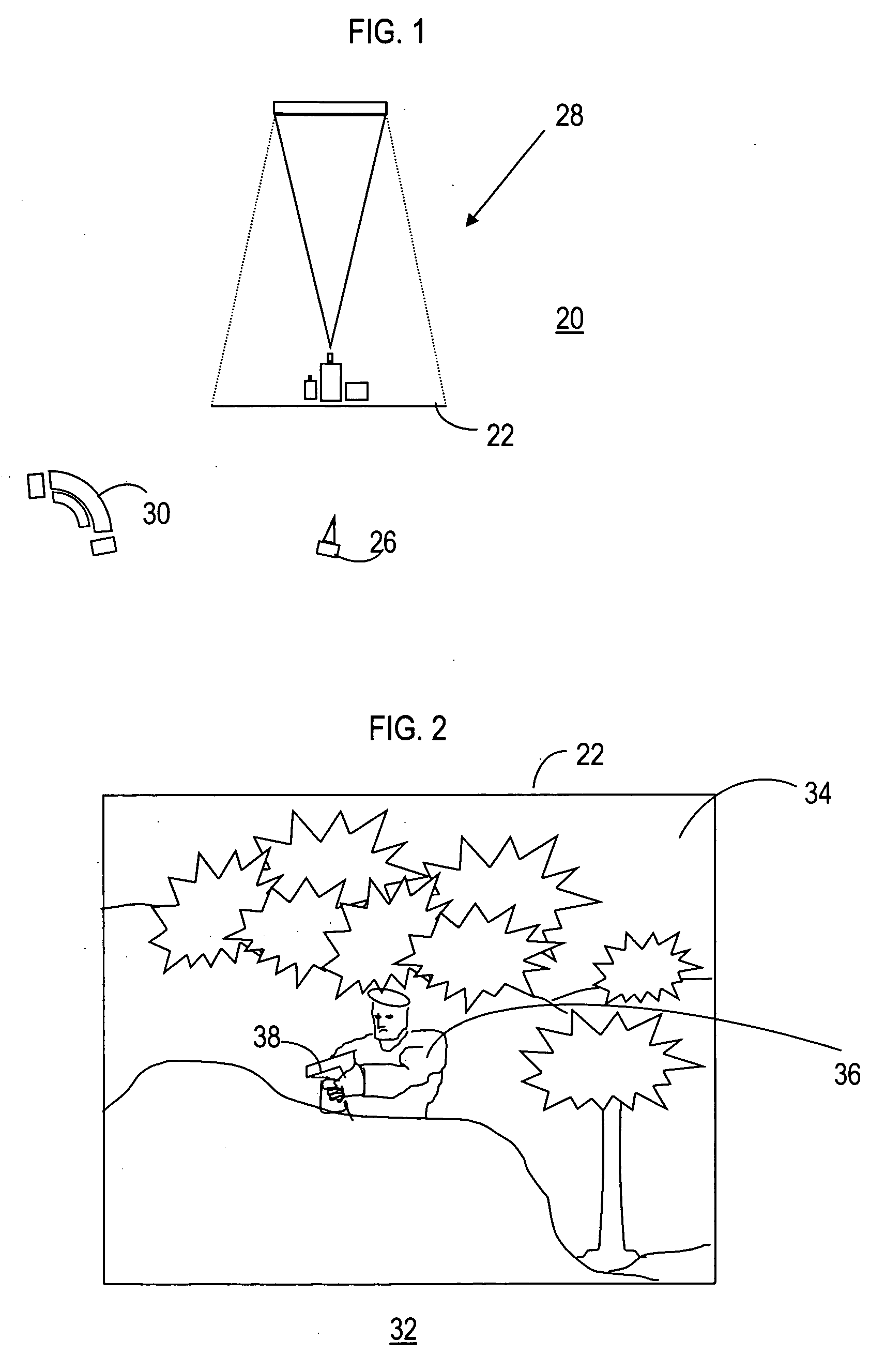
[0025] The present invention entails a system for simulating a threat fire condition that may be utilized within a simulation system for use-of-force training. The simulation system is utilized to display a scenario, with the scenario including an offender holding a weapon. The term “threat fire” utilized herein refers to a situation within the pre-recorded scenario in which the offender discharges his or her weapon toward the trainee, i.e., the offender is a “threat” to the trainee's perceived safety.

[0026]FIG. 1 shows a block diagram of a simulation system 20 in which the present invention may be implemented. Simulation system 20 includes a single screen 22, in front of which one or more participants, i.e., a trainee 26, may be positioned. A rear projection system 28 is associated with screen 22. Trainee 26 views screen 22 with video projected thereon via rear projection system 28, and must decide how to react to the subject matter presented within the video. Rear projection syst...


PUM


Abstract

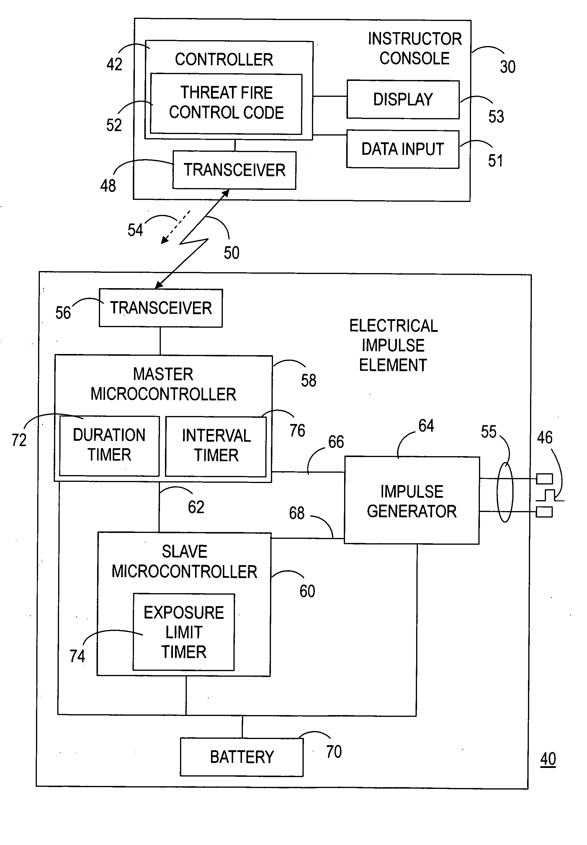
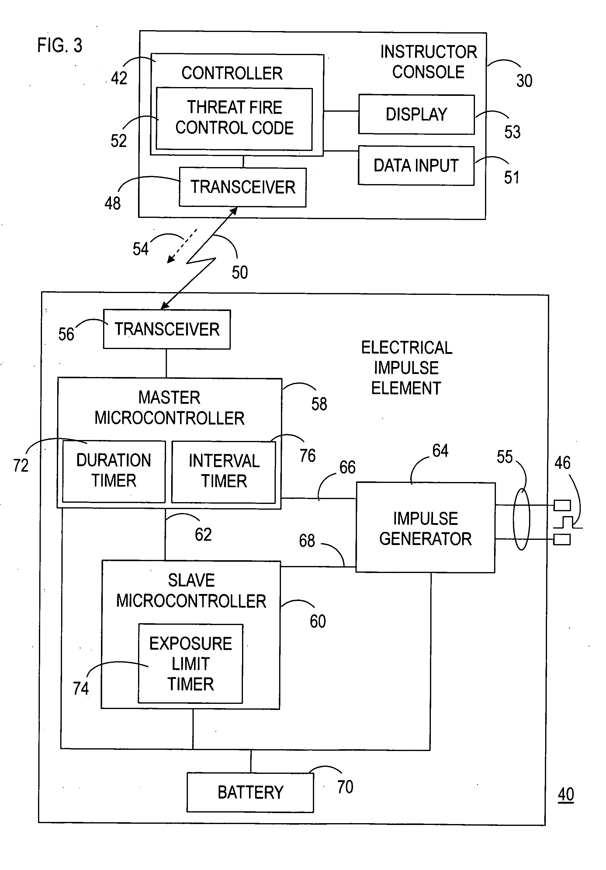
A threat fire simulation system (40) for simulating a projectile impacting a user (26) includes an electrical impulse element (44) configured for physical contact with the user (26). A controller (42) is in communication with the electrical impulse element (44). The controller (42) enables receipt of a signal (54) for activating electrical impulse element (44) to deliver a non-disabling electrical pulse (46) to the user (26). The electrical pulse (46) simulates an impact of the projectile on the user (26).

Description

RELATED INVENTION [0001] In addition, the present invention claims priority under 35 U.S.C. §119(e) to: “Simulated Shot-Back Training Device,” U.S. Provisional Patent Application Ser. No. 60 / 633,080, filed 3 Dec. 2004, which is incorporated by reference herein.TECHNICAL FIELD OF THE INVENTION [0002] The present invention relates to the field simulation systems for use-of-force training. More specifically, the present invention relates to the simulation of a projectile, such as a bullet, impacting a trainee. BACKGROUND OF THE INVENTION [0003] Due to current world events, there is an urgent need for highly effective law enforcement, security, and military training. Training involves practicing marksmanship skills with lethal and / or non-lethal weapons. Additionally, training involves the development of decision-making skills in situations that are stressful and potentially dangerous. Indeed, perhaps the greatest challenges faced by a trainee are when to use force and how much force to ...

Claims


Application Information

Patent Timeline
Patent Type & Authority Applications(United States)
IPC IPC(8): F41A33/00
CPCF41A33/00
Inventor FERRIS, ROBERT D.MALIN, ROGER D.
Owner VIRTRA INC
Learn More