
System and method for location based remote services

Inactive Publication Date: 2006-06-08
GE MEDICAL SYST GLOBAL TECH CO LLC
View PDF6 Cites 108 Cited by
  • Summary
  • Abstract
  • Description
  • Claims
  • Application Information

AI Technical Summary

Benefits of technology

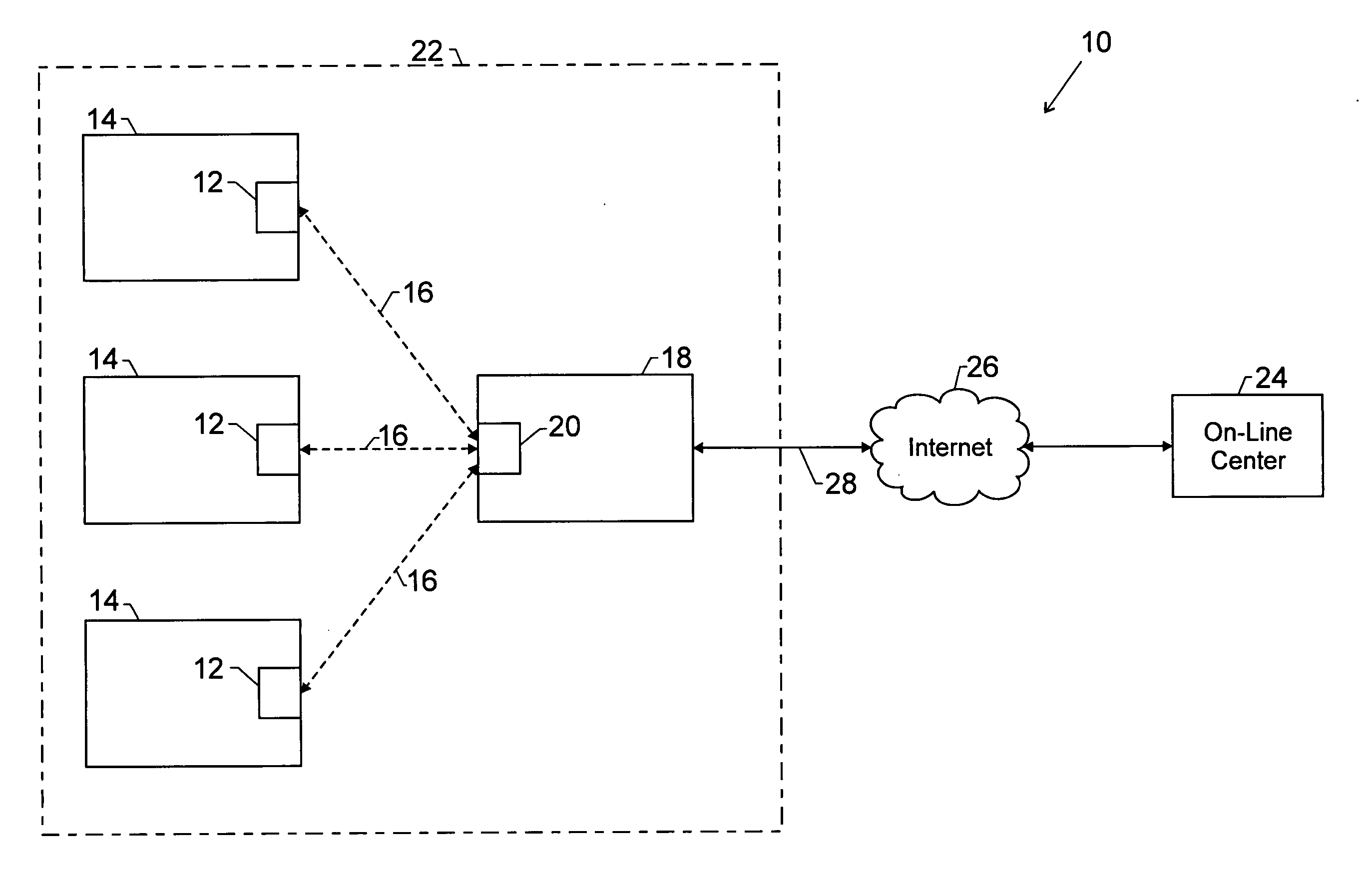
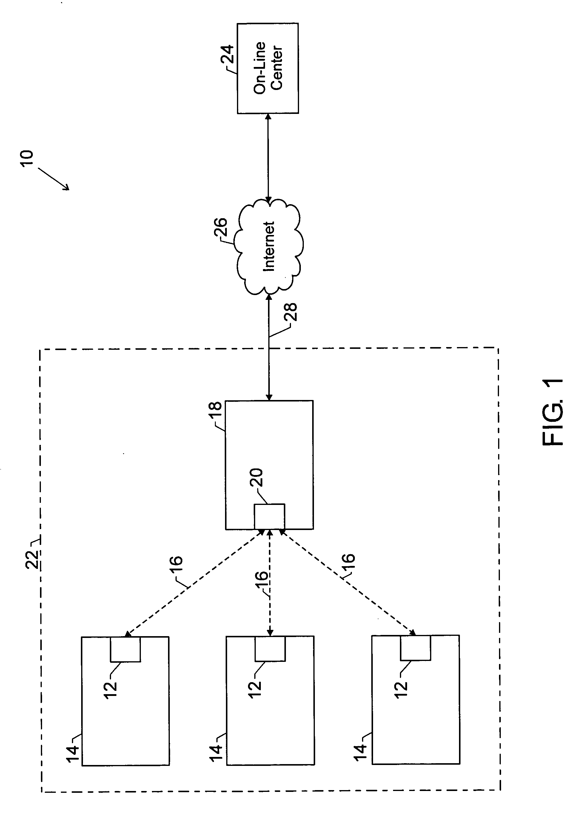
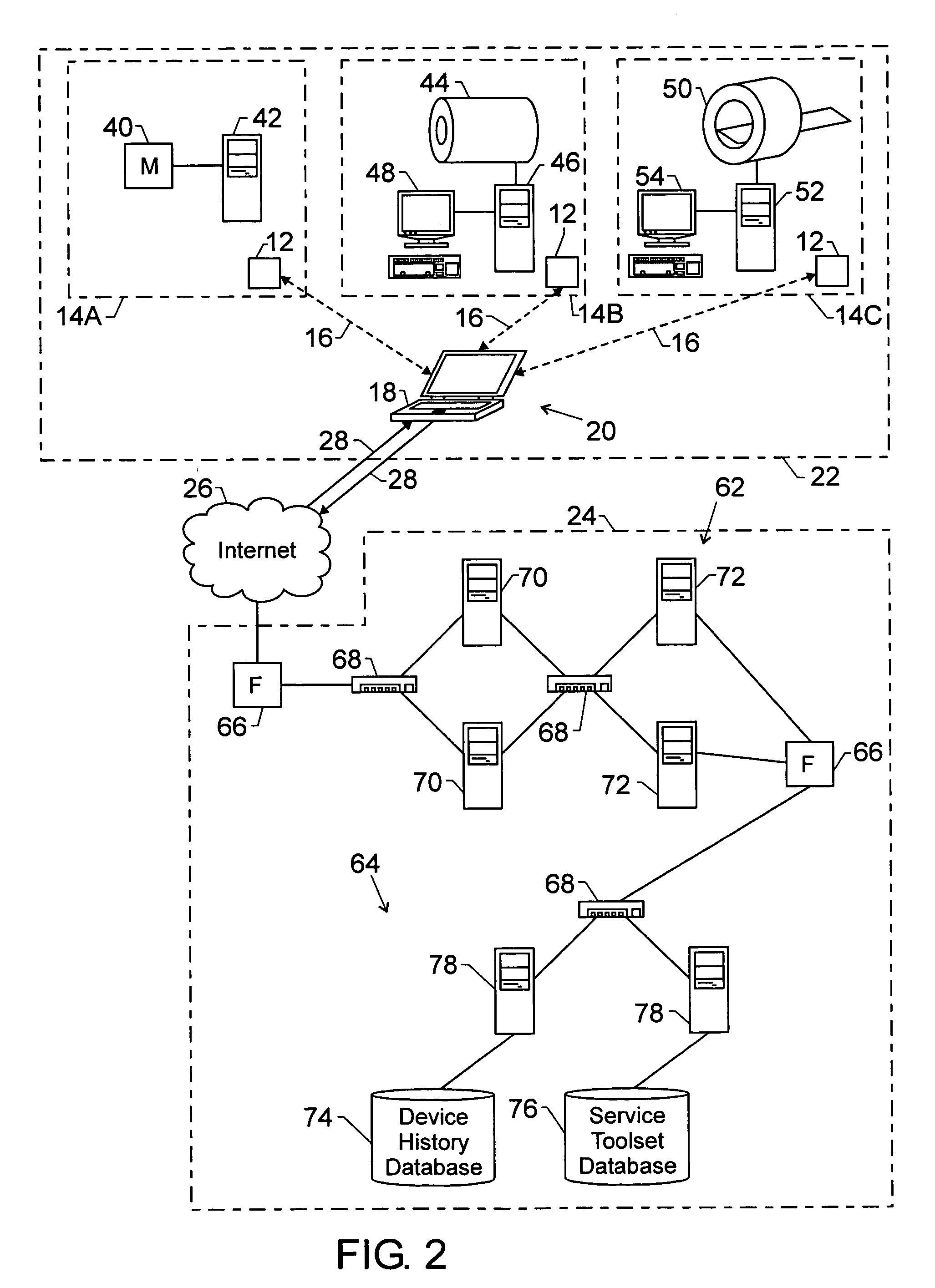
[0007] To accommodate detection of a medical system component and the formation of a location-based network, the technique equips medical systems and components, such as imaging systems and their scanners and / or computers, with a passive or quasi-passive wireless communication device which responds in the presence of a transmitter carried by a field engineer. The passive wireless devices may operate on radio frequency (RF), optical, acoustic, and so on. When in close proximity, the medical system or component may be added to a field-engineer (FE) network and / or location-based (e.g., ad hoc) network. The field engineer can then perform service with a standard electronic toolset, for example. It should be noted that the passive or quasi-passive device may be more operational or active than passive RF tags containing identification information, for example. On the other hand, the device may be passive in the sense of not actively emitting a wireless signal unless responding to an authenticated wireless signal initiated by the FE transmitter. Such infrequent wireless emission and intermittent wireless connection enhances the efficiency and security of servicing and communicating with the medical system.

Problems solved by technology

However, many medical systems, such as medical imaging systems, are complex machines.
However, specific medical systems may be difficult to locate and find in the medical facility.
This may be especially problematic for stand-alone medical systems (and components) not connected to a network.
For example, lack of connection of the medical system to a medical facility information system, a local area network, the Internet, and so on, may prohibit or make difficult identifying and servicing the medical system, on-site or remotely.
With movement of the medical system components, such as during shipping, warehousing, and installation of new or relocated components, as well as with mobile systems that may be stored in various rooms and locations, the field engineer may find it challenging to locate the medical system.
Further, once the system or device is found, it may be difficult to identify relevant aspects of the device, such as service contractual information, current repair status, machine state and service history.
Furthermore, as indicated, stand-alone devices not connected to a network and / or not configured to couple to an external processor-based system may not benefit from on-site / remote electronic services.

Method used


Image

  • System and method for location based remote services
  • System and method for location based remote services
  • System and method for location based remote services

Examples


Embodiment Construction

[0018] To accommodate detection of a medical system component and formation of a location-based network, the technique equips medical systems and components, such as imaging systems and their scanners, with a passive or quasi-passive communication device which responds in the presence of a transmitter. Again, such passive devices may operate on radio frequency (RF), optical, acoustic, and so on. A service provider or field engineer (FE) may carry the transmitter (e.g., laptop, transceiver, antennae, wireless network card, 802.11b device, etc.) to search for a response from the passive communication device (e.g., receiver, transceiver, antennae, wireless network card, 802.11b device, etc.) disposed on a component of the medical system or disposed in the medical system as an independent item. When in close proximity, the medical system or component may be added to a field-engineer network. The field engineer can then perform service with a standard electronic tool set, for example. Ag...


PUM


Abstract

A system and method for locating and servicing a medical device. A portable computer system transmits a wireless signal to physically locate and identify the medical device which is disposed in proximity to the portable computing system. Further, the medical device may be wirelessly coupled to the portable computer system. The device may be serviced by a field engineer and / or a remote servicing center via the portable computing system and the wireless connection. An electronic toolset may be employed.

Description

BACKGROUND [0001] The invention relates generally to the field of equipment services. More particularly, the invention relates to techniques for locating, identifying, and servicing medical systems within a medical facility or institution. [0002] There are many different electronic devices available for learning about and treating patient conditions in the medical field. Over recent decades, more sophisticated systems have been developed that include various types of electrical data acquisition which detect and record the operation of systems of the body and, to some extent, the response of such systems to situations and stimuli. Even more sophisticated systems have been developed that provide images of the body, including internal features which could only be viewed and analyzed through surgical intervention before their development, and which permit viewing and analysis of other features and functions which could not have been seen in any other manner. All of these techniques have...

Claims


Application Information

Patent Timeline
IPC IPC(8): A61B5/05
CPCA61B5/055A61B6/032A61B6/56A61B2560/0271G16H40/40G16H40/67
Inventor SIEVENPIPER, CRISPIAN LEEWILEY, SANDRA FIELDSTAD
Owner GE MEDICAL SYST GLOBAL TECH CO LLC
Learn More