

System for analyzing the geometry of a radiation treatment apparatus, software and related methods
a radiation treatment apparatus and geometry analysis technology, applied in the field of radiation therapy, can solve the problems of not being able to deliver the radiation dose to the correct location within the patient's body, using the necessary effective radiation dose, and serious complications, and achieve the effect of improving the accuracy of the detector/determiner subsystem, accurate reference position and and accurate orientation of the isocenter coordinate system
- Summary
- Abstract
- Description
- Claims
- Application Information
AI Technical Summary
Benefits of technology
Problems solved by technology
Method used
Image

Examples
Embodiment Construction
[0045] The present invention will now be described more fully hereinafter with reference to the accompanying drawings, which illustrate embodiments of the invention. This invention may, however, be embodied in many different forms and should not be construed as limited to the illustrated embodiments set forth herein. Rather, these embodiments are provided so that this disclosure will be thorough and complete, and will fully convey the scope of the invention to those skilled in the art. Like numbers refer to like elements throughout. Prime notation, if used, indicates similar elements in alternative embodiments.
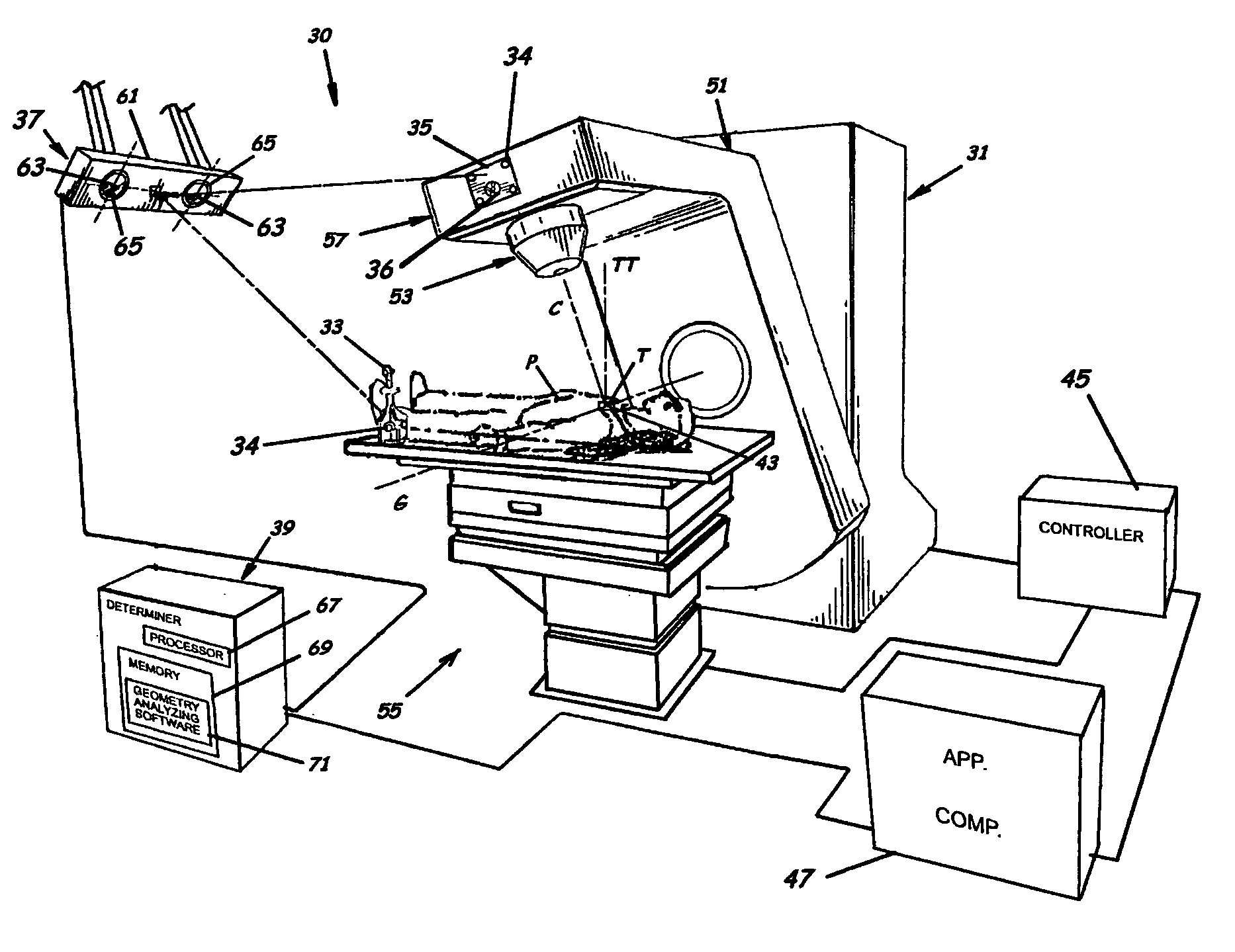
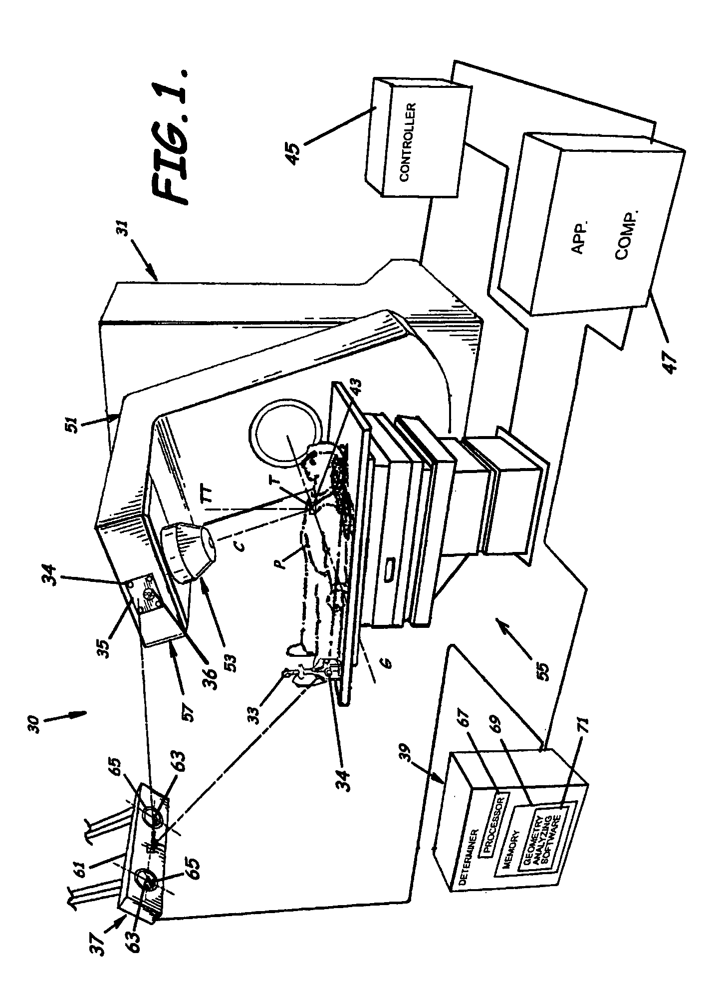
[0046] Successful therapy treatments, such as, for example, radiation therapy, rely on the ability to accurately locate and define a radiation beam. The spatial position of the radiation beam is defined by the physical geometry of the radiation treatment apparatus. Embodiments of the present invention analyze the geometry of rotating assemblies of the radiation treatment appa...
PUM
 Abstract
Description
Claims
Application Information