Device and method for selectively controlling the utility of a target

a target and utility technology, applied in the field of target utility selective control, can solve the problems of not being able to account for products in the middle of a pallet, products buried in a consumer's cart, slow adoption of rfid, etc., and achieve the effects of improving rf reception, providing robust rf communication, and economically installing

Inactive Publication Date: 2006-06-08
NXP BV
View PDF97 Cites 44 Cited by
  • Summary
  • Abstract
  • Description
  • Claims
  • Application Information

AI Technical Summary

Benefits of technology

[0012] Briefly, the present invention provides a radio frequency controller device that enables the utility of a target to be controlled using an RF communication. The radio frequency controller device has a switch that is set to a defined state responsive to the RF communication. More particularly, conditional logic circuitry uses the RF communication to determine if the target's utility should be changed, and sets the state of the switch accordingly. The radio frequency controller device also has a target interface that allows the target to determine the state of the switch, and based on the state of the switch, a different utility will be available for the target. The radio frequency controller device also has an antenna for the RF communication, as well as a demodulator/modulator circuit. When used to control the utility of an electrical or electronic device, the radio frequency controller device has a low-power circuit portion that is used to set the state of the switch responsive to the RF communication, and also has a full power circuit portion that communicates with the target. In this way, the state of the switch may be set when the target is in a power-off condition, and the target is able to determine the state of the switch when the target is activated.
[0013] In one arrangement, the radio frequency controller device has an internal module inside the target, and an external module outside the target. The external module has the antenna, so the antenna is able to robustly provided RF communication. The external module may electrically and mechanically connect to the target through a connector, such as a custom connector, power connector, audio connector, or video connector. In some cases, the connector may not sufficiently pass RF signals, so the RF signal is demodulated to a lower frequency using circuitry on the external module. Also, some standard connectors are likely to connect to target operating circuit...

Problems solved by technology

However, bar code readers require a line-of-site reading, so can not, for example, account for products in the middle of a pallet, or for products buried in a consumer's cart.
Unfortunately, RFID has been slow to be adopted, due to the relatively high cost of RFID tags themselves, and to limitations in reading the RFID tags.
This not only limits where on a product package an RFID label may be placed, but also causes errors when a product is placed in a position where the label is shielded from the RF reader.
Theft is also serious and growing problem in the distribution of products.
Devices, such as digital cameras, DVD players, MP3 players, and game devices are popular targets of theft, not only in the retail store by consumers, but also by others in the distribution chain.
Other types of products are also subject to theft, such as DVDs, CDs, game discs, game cartridges, and other types of media.
From the facility where they are manufactured to the retail point-of-sale (POS) where they are sold many high-value consumer products are vulnerable to theft.
Despite these efforts theft of high-value targets such as DVD's, CD's and video games; portable video game players, DVD players, digital cameras, computers, printers, televisions and the like cost manufacturers and retailers billions of dollars per year.
Such rampant theft increase the cost of manufacturing, shipping, and selling of products.
Each entity in the distribution chain is at risk for theft, and must take steps to reduce or control the level of theft.
This cost is ultimately borne by the legitimate purchaser, which places an unfair “theft...

Method used


Image

  • Device and method for selectively controlling the utility of a target
  • Device and method for selectively controlling the utility of a target
  • Device and method for selectively controlling the utility of a target

Examples


Embodiment Construction

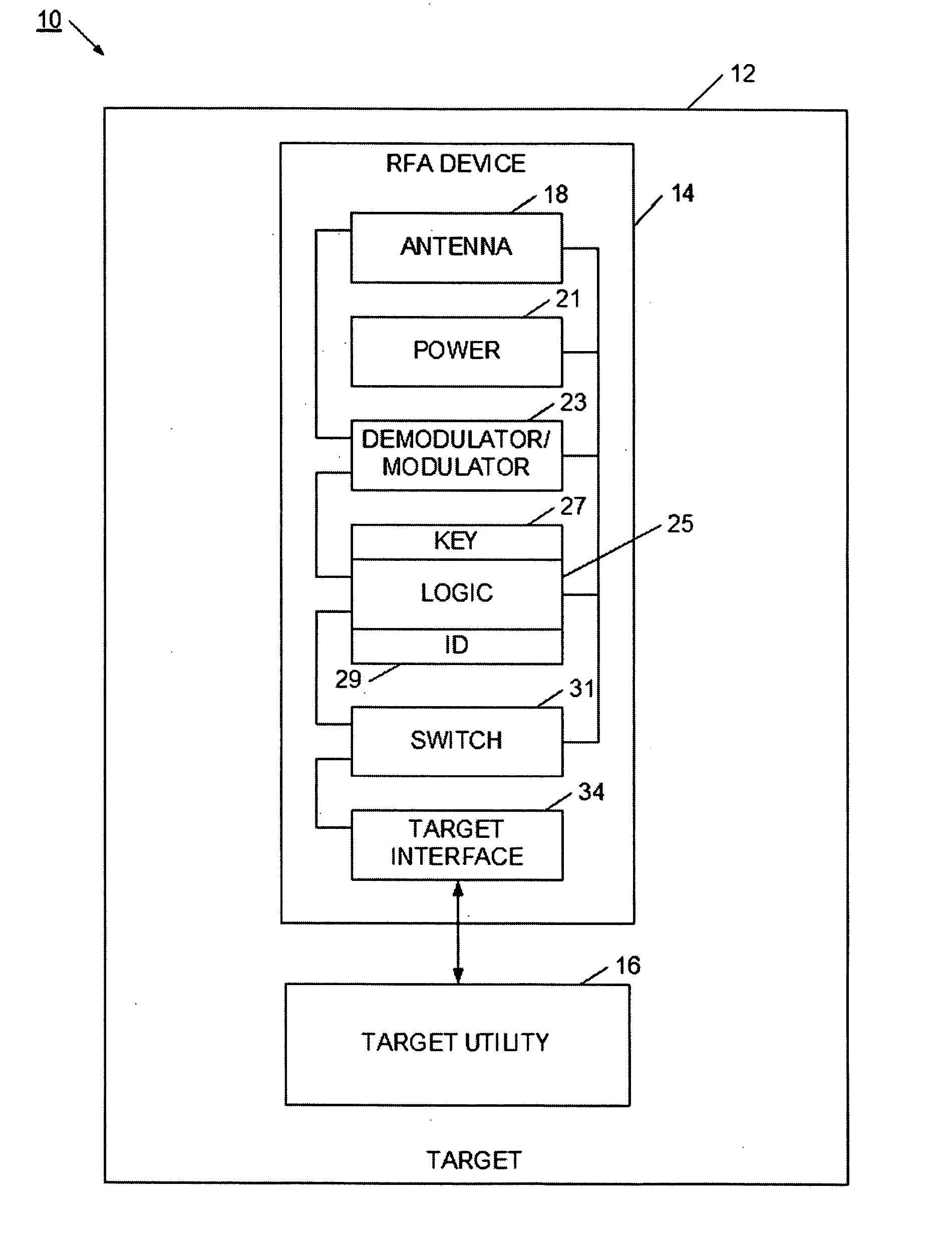
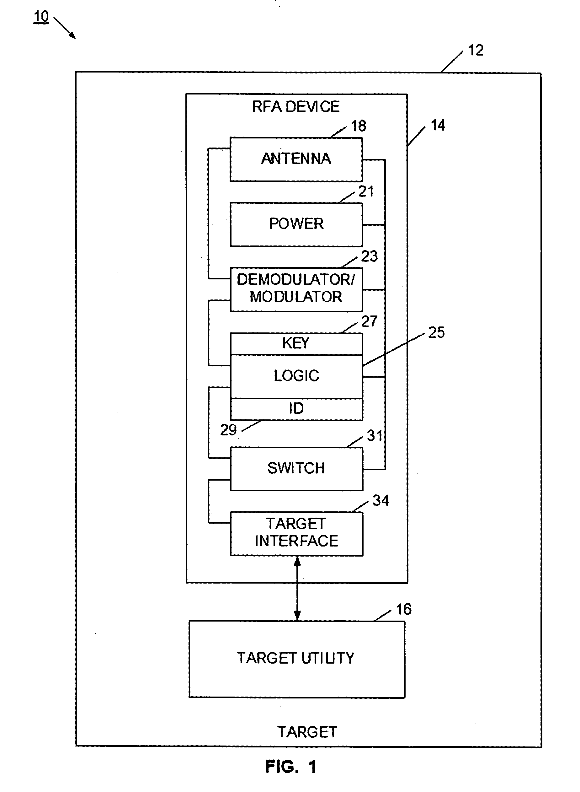
[0041] Referring now to FIG. 1, a target device 10 is illustrated. Target device 10 includes a radio frequency activation (RFA) device 14 within the housing 12 of the target. The RFA device is used for controlling the utility of the target 10. To facilitate ease of manufacture, the RFA device 14 is provided in a package convenient for large-scale production. For example, the RFA device may be in the form of an integrated circuit package, or in the form of a surface mount device. Either way, the RFA device may be easily designed into a target's circuitry or logic, and may be readily installed on a printed circuit board or other substrate. In this way, the RFA device may be included with a target device in a cost effective manner. It will be appreciated that the RFA device may be provided in other manufacture-friendly forms.

[0042] Target 10 may be an electronic device such as a computer, TV, appliance, MP3 player, camera, game counsel, or toy. In another example, the target may be a ...


PUM


Abstract

A radio frequency controller device enables the utility of a target to be controlled using an RF communication. The radio frequency controller device has a switch that is set to a defined state responsive to the RF communication. More particularly, conditional logic circuitry uses the RF communication to determine if the target's utility should be changed, and sets the state of the switch accordingly. The radio frequency controller device also has a target interface that allows the target to determine the state of the switch, and based on the state of the switch, a different utility will be available for the target. The radio frequency controller device also has an antenna for the RF communication, as well as a demodulator/modulator circuit. When used to control the utility of an electrical or electronic device, the radio frequency controller device has a low-power circuit portion that is used to set the state of the switch responsive to the RF communication, and also has a full power circuit portion that communicates with the target. In this way, the state of the switch may be set when the target is in a power-off condition, and the target is able to determine the state of the switch when the target is activated.

Description

RELATED APPLICATIONS [0001] The present application claims priority to U.S. provisional patent application 60 / 633,971, filed Dec. 7, 2004, entitled “A Method and Means of RF Activation of a Target”; to U.S. provisional patent application 60 / 654,384, filed Feb. 18, 2005, entitled “A Method and Means of RF Activation of a Target”; to U.S. patent application Ser. No. 11 / 259,578, filed Oct. 26, 2005, entitled “Method and System for Selectively Controlling the Utility a Target”; and to U.S. patent application Ser. No. 11 / 259,185, filed Oct. 26, 2005, entitled “Method and Network for Selectively Controlling the Utility a Target”, all of which are incorporated herein by reference as if set forth in their entirety. This application is also related to copending U.S. patent application Ser. No. ______, filed ______, and entitled “______”; and to U.S. patent application Ser. No. ______, filed ______, and entitled “______”; which are also incorporated herein by reference.BACKGROUND [0002] 1. Fi...

Claims


Application Information

Patent Timeline
IPC IPC(8): G06F17/00G06F7/00
CPCG06Q20/206G07C9/00309G08B13/2417G08B21/0213G08C17/02H04B5/0056H04L63/0428H04L63/08H04L9/0894H04L2209/805Y02D30/70G06Q20/20G08C19/00
Inventor ATKINSON, PAULCONERO, RONALD S.
Owner NXP BV
Why Eureka
Try Eureka