
Device and method for selectively controlling the utility of an integrated circuit device

a technology of integrated circuit and utility, which is applied in the direction of program control, testing/monitoring control system, instruments, etc., can solve the problems of not being able to account for products in the middle of a pallet, products buried in a consumer's cart, and slow adoption of rfid, so as to improve rf reception, provide robust rf communication, and economically install

Inactive Publication Date: 2006-08-31
NXP BV
View PDF94 Cites 127 Cited by
  • Summary
  • Abstract
  • Description
  • Claims
  • Application Information

AI Technical Summary

Benefits of technology

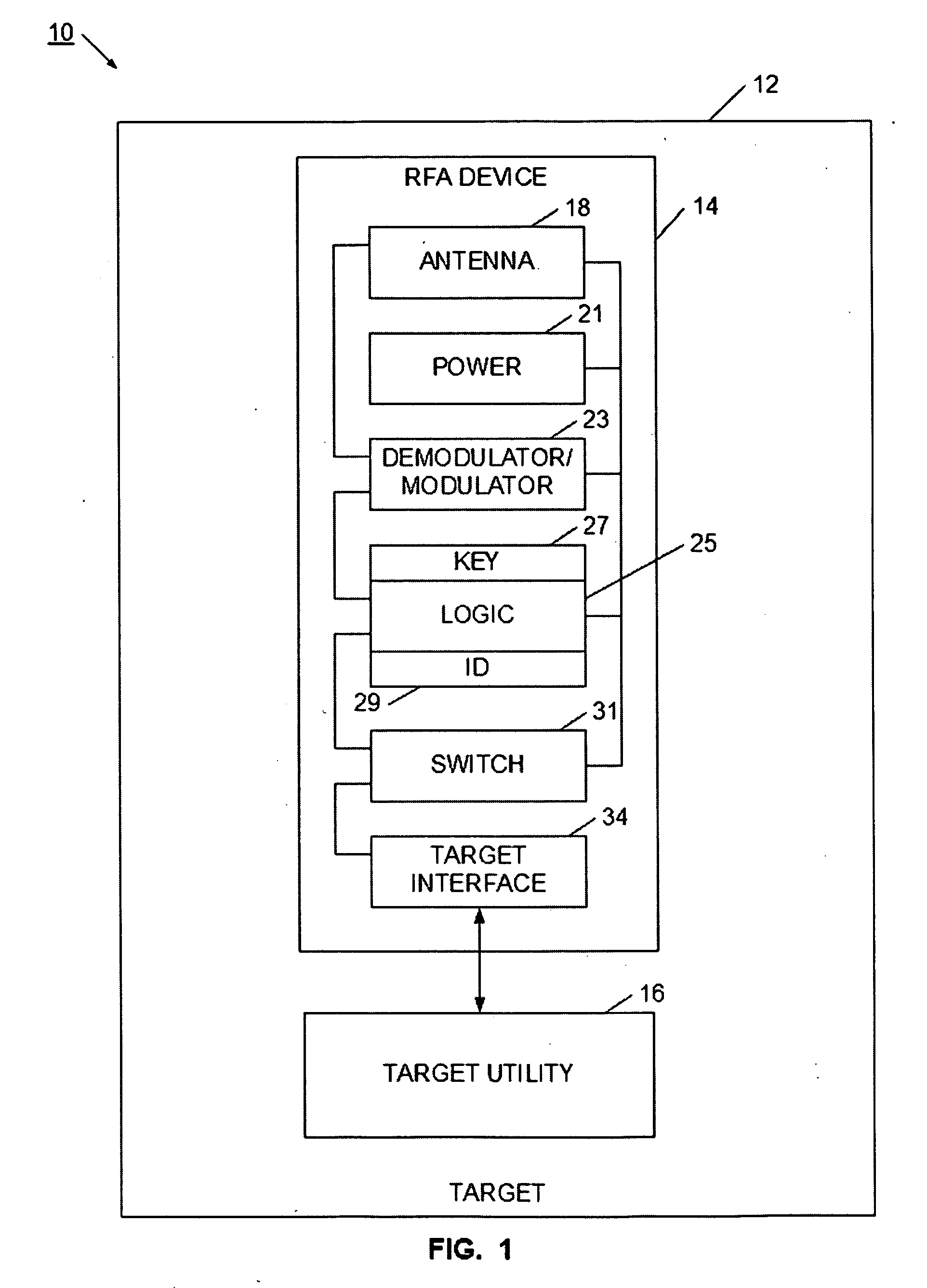
[0018] Briefly, the present invention provides a radio frequency controller device that enables the utility of a target to be controlled using an RF communication. The radio frequency controller device has a switch that is set to a defined state responsive to the RF communication. More particularly, conditional logic circuitry uses the RF communication to determine if the target's utility should be changed, and sets the state of the switch accordingly. The radio frequency controller device also has a target interface that allows the target to determine the state of the switch, and based on the state of the switch, a different utility will be available for the target. The radio frequency controller device also has an antenna for the RF communication, as well as a demodulator / modulator circuit. When used to control the utility of an electrical or electronic device, the radio frequency controller device has a low-power circuit portion that is used to set the state of the switch responsive to the RF communication, and also has a full power circuit portion that communicates with the target. In this way, the state of the switch may be set when the target is in a power-off condition, and the target is able to determine the state of the switch when the target is activated.
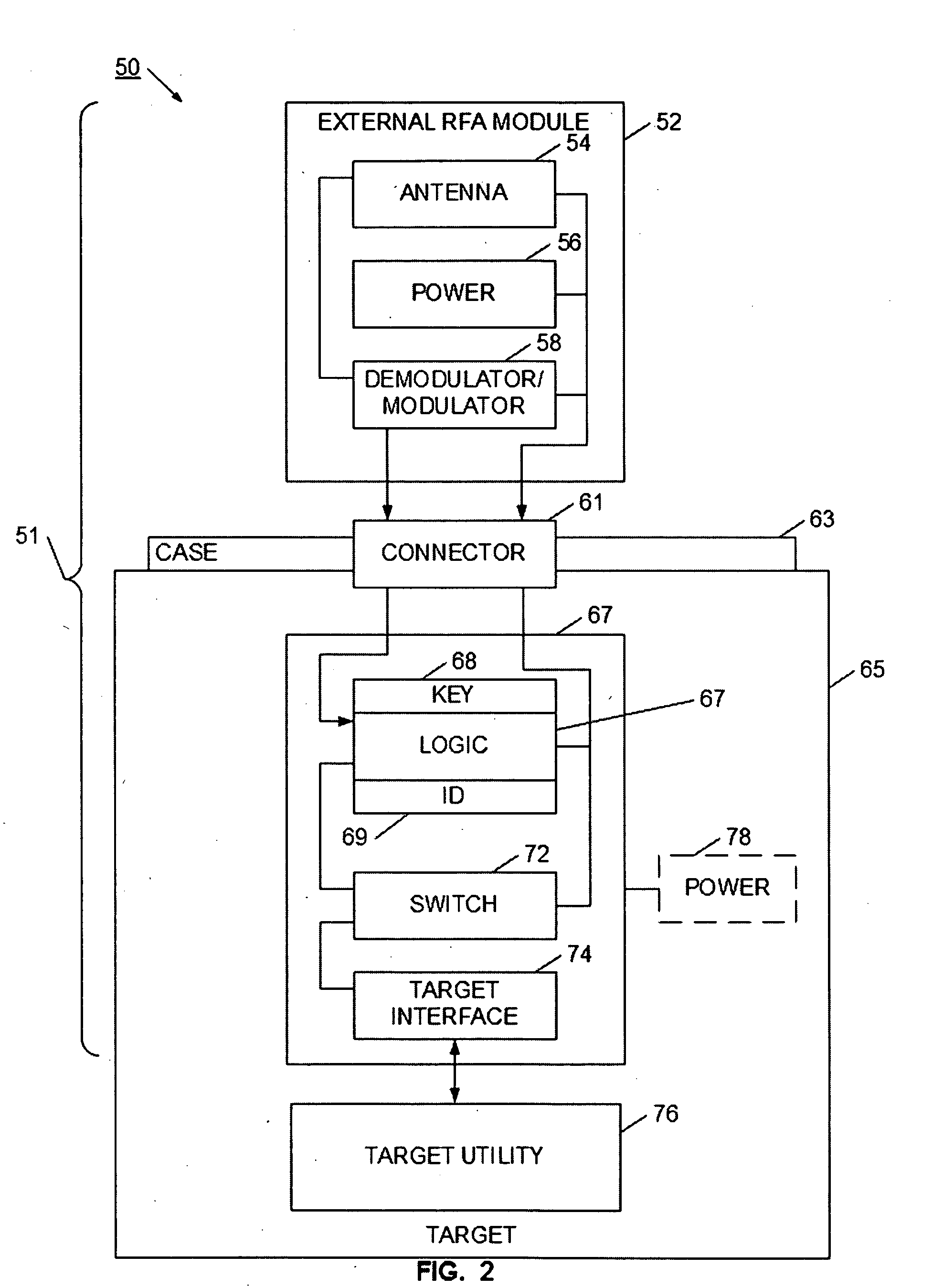
[0019] In one arrangement, the radio frequency controller device has an internal module inside the target, and an external module outside the target. The external module has the antenna, so the antenna is able to robustly provided RF communication. The external module may electrically and mechanically connect to the target through a connector, such as a custom connector, power connector, audio connector, or video connector. In some cases, the connector may not sufficiently pass RF signals, so the RF signal is demodulated to a lower frequency using circuitry on the external module. Also, some standard connectors are likely to connect to target operating circuitry, so an isolation circuit may be useful to properly route signals between the external module and the internal module. The isolation circuit may also be useful to protect radio frequency controller device circuits from effects of the target circuit, as well as protect the target circuits from effects of the radio frequency controller device. The radio frequency controller device may be constructed, for example, as an integrated circuit DIP package, a surface mount package, silicon die, or as a printed circuit.
[0020] Advantageously, the disclosed radio frequency controller device enables an RF device to selectively change the utility of a target. The radio frequency controller device may be readily incorporated into targets such as electrical or electronic devices, so enables adaptable manufacturing process, flexible distribution accounting, and a denial-of-benefit security system. Since the radio frequency controller device may be constructed as commonly used surface mount or DIP packages, the radio frequency controller device may be economically installed in many electronic, electrical, and media devices. Also, the radio frequency controller device may be constructed as a single package, or may be constructed as an internal module connected to an external module, which allows for the flexible positioning of device components. In this way, components that need RF communication capability may be placed in areas with improved RF reception. By separating the antenna or other RF-sensitive components from other logic circuitry, more robust detection is enabled. Also, the increased placement flexibility enables an RF control capability for a wider range of products, and allows for a more aesthetically appealing arrangement of components. For example, the externally visible portions of the radio frequency controller device may be made smaller and less intrusive, with the memory and logic portions placed in an out-of-sight location.

Problems solved by technology

However, bar code readers require a line-of-site reading, so can not, for example, account for products in the middle of a pallet, or for products buried in a consumer's cart.
Unfortunately, RFID has been slow to be adopted, due to the relatively high cost of RFID tags themselves, and to limitations in reading the RFID tags.
This not only limits where on a product package an RFID label may be placed, but also causes errors when a product is placed in a position where the label is shielded from the RF reader.
Theft is also serious and growing problem in the distribution of products.
Devices, such as digital cameras, DVD players, MP3 players, and game devices are popular targets of theft, not only in the retail store by consumers, but also by others in the distribution chain.
Other types of products are also subject to theft, such as DVDs, CDs, game discs, game cartridges, and other types of media.
In another example, microprocessors and other advanced integrated circuit devices are easy targets for theft.
These advanced integrated circuit devices are small, expensive, and are easily sold in a “black” market, or readily incorporated into a thief's system or product.
It is particularly difficult to implement an anti-theft circuit or scheme with these advanced integrated circuit devices.
First, these advanced integrated circuits may be sold boxed separately, and in this state will have no power for activating an anti-theft circuit.
Second, it is risky to have a clerk handle a circuit to disable any anti-theft mechanism.
These devices are extremely sensitive to ESD (electro-static discharge), and unless strict anti-static processes are carefully followed, a clerk can easily destroy the device in the handling process.
Third, it is often commercially impractical to modify an integrated circuit to incorporate an anti-theft scheme.
Some devices, such as advanced microprocessors, take years to design and implement, and would require substantial modifications of masks and processes, as well as additional and costly manufacturing steps.
Further, there is limited space and power on these processors, and their designers already compete to add more advanced functionality, and thus would be highly resistant to dedicating scarce space and power to any new anti-theft circuitry.
Any change to the pin or grid arrangement, or any violation of the size restrictions, could cause a substantial redesign effort for Intel's customers.
From the facility where they are manufactured to the retail point-of-sale (POS) where they are sold many high-value consumer products are vulnerable to theft.
Despite these efforts theft of high-value targets such as DVD's, CD's and video games; portable video game players, DVD players, digital cameras, computers, printers, televisions and the like cost manufacturers and retailers billions of dollars per year.
Such rampant theft increase the cost of manufacturing, shipping, and selling of products.
Each entity in the distribution chain is at risk for theft, and must take steps to reduce or control the level of theft.
This cost is ultimately borne by the legitimate purchaser, which places an unfair “theft tax” on purchased products.
Also, since may products are so easily stolen from a retail environment, retailers must take extraordinary steps to secure products.
For example, DVDs, CDs, and small electronic devices are often packaged in oversized holders to make them more difficult to hide.
These holders, however, also interfere with a consumers ability to interact with the product, ultimately making the product less attractive to the consumer.
In another example, retail stores may place their most valuable and easily stolen products in locked cases.
In this way, retail consumers are completely distanced from these products, which reduces theft, but also makes the products difficult to purchase.
This process may be dangerous for the guard or clerk, and, since many of the alarms are false, causes undo stress for law-abiding consumers.
None of these attempts to stop retail theft has worked, and all make the retail experience less attractive to the consumer.
Further, neither the oversized holders, the locked cases, nor the guards address the significant level of theft that occurs between the manufacturer's dock to the retail shelf.
The distribution of products faces other challenges.
Although this is desirable from the consumer's standpoint, it complicates the manufacturing, shipping, inventorying, shelving, and retailing processes.
This problem exists in the configuration of electronic products, computers, gaming systems, DVDs, CDs, game cartridges, for example.
A similar problem exists with feature sets for games, computers, and other products.
Challenges also exist for non-commercial distribution of goods.

Method used


Image

  • Device and method for selectively controlling the utility of an integrated circuit device
  • Device and method for selectively controlling the utility of an integrated circuit device
  • Device and method for selectively controlling the utility of an integrated circuit device

Examples


Embodiment Construction

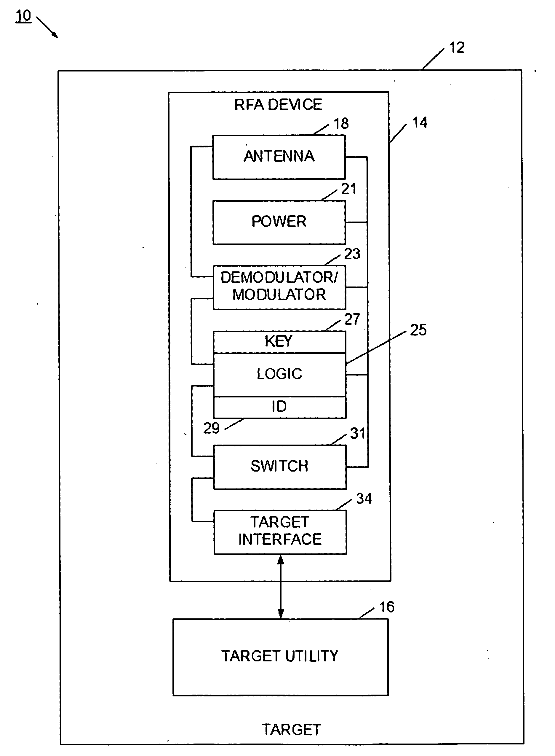
[0051] Referring now to FIG. 1, a target device 10 is illustrated. Target device 10 includes a radio frequency activation (RFA) device 14 within the housing 12 of the target. The RFA device is used for controlling the utility of the target 10. To facilitate ease of manufacture, the RFA device 14 is provided in a package convenient for large-scale production. For example, the RFA device may be in the form of an integrated circuit package, or in the form of a surface mount device. Either way, the RFA device may be easily designed into a target's circuitry or logic, and may be readily installed on a printed circuit board or other substrate. In this way, the RFA device may be included with a target device in a cost effective manner. It will be appreciated that the RFA device may be provided in other manufacture-friendly forms.

[0052] Target 10 may be an electronic device such as a computer, TV, appliance, MP3 player, camera, game counsel, or toy. In another example, the target may be a ...


PUM


Abstract

A radio frequency controller device enables the utility of a target to be controlled using an RF communication. The radio frequency controller device has a switch that is set to a defined state responsive to the RF communication. More particularly, conditional logic circuitry uses the RF communication to determine if the target's utility should be changed, and sets the state of the switch accordingly. The radio frequency controller device also has a target interface that allows the target to determine the state of the switch, and based on the state of the switch, a different utility will be available for the target. The radio frequency controller device also has an antenna for the RF communication, as well as a demodulator / modulator circuit. When used to control the utility of an electrical or electronic device, the radio frequency controller device has a low-power circuit portion that is used to set the state of the switch responsive to the RF communication, and also has a full power circuit portion that communicates with the target. In this way, the state of the switch may be set when the target is in a power-off condition, and the target is able to determine the state of the switch when the target is activated.

Description

RELATED APPLICATIONS [0001] The present application claims priority to U.S. provisional patent application 60 / 654,384, filed Feb. 18, 2005, entitled “A Method and Means of RF Activation of a Target”; and is also a continuation-in-part to co-pending U.S. patent application Ser. No. 11 / 296,082 filed Dec. 7, 2005 and entitled “Method and System for Identifying a Target”; to U.S. patent application Ser. No. 11 / 296,547 filed Dec. 7, 2005 and entitled “Device and Method for Selectively Controlling a Processing Device”; to U.S. patent application Ser. No. 11 / 296,081 filed Dec. 7, 2005 and entitled “Device and Method for Selectively Controlling the Utility of a Target”; and to U.S. patent application Ser. No. 11 / 295,867 filed Dec. 7, 2005 and entitled “Device and Method for Selectively Activating a Target”; all of which are incorporated herein by reference.BACKGROUND [0002] 1. Field [0003] The present invention relates to a target that is enabled to have its utility controlled using RF comm...

Claims


Application Information

Patent Timeline
Patent Type & Authority Applications(United States)
IPC IPC(8): G05B19/00
CPCG06F21/88G08C17/02
Inventor ATKINSON, PAULCONERO, RONALD S.KRUEST, JAMES R.
Owner NXP BV
Learn More