
Air conditioner

a technology for air conditioners and compressors, applied in the field of air conditioners, can solve the problems of increasing power consumption, affecting the efficiency of conventional air conditioners, so as to reduce the difference between the suction and discharge pressure of compressors, reduce the compression load, and reduce the condensation pressure

Inactive Publication Date: 2006-06-15
LG ELECTRONICS INC
View PDF34 Cites 1 Cited by
  • Summary
  • Abstract
  • Description
  • Claims
  • Application Information

AI Technical Summary

Benefits of technology

The present invention provides an air conditioner that reduces power consumption and improves efficiency by reducing the difference between the suction and discharge pressures of the compressor. This is achieved by using a pressurizer to pressurize the suction-side refrigerant, which in turn reduces the load on the compressor. An auxiliary condenser may also be used to further reduce the pressure difference between the discharge-side refrigerant and the suction-side refrigerant. The pressurizer may include a heat exchanger to cause the suction-side refrigerant to heat-exchange with the condensed refrigerant. Overall, the air conditioner of the present invention provides a more efficient and effective solution for reducing power consumption and improving efficiency.

Problems solved by technology

When the difference between suction and discharge pressures increases, an increase in power consumption occurs.
In this regard, the conventional air conditioner has a problem of a degradation in system efficiency.

Method used


Image

  • Air conditioner
  • Air conditioner
  • Air conditioner

Examples


first embodiment

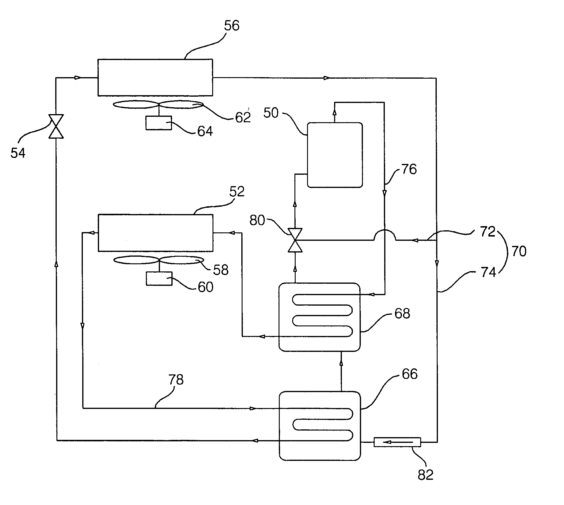
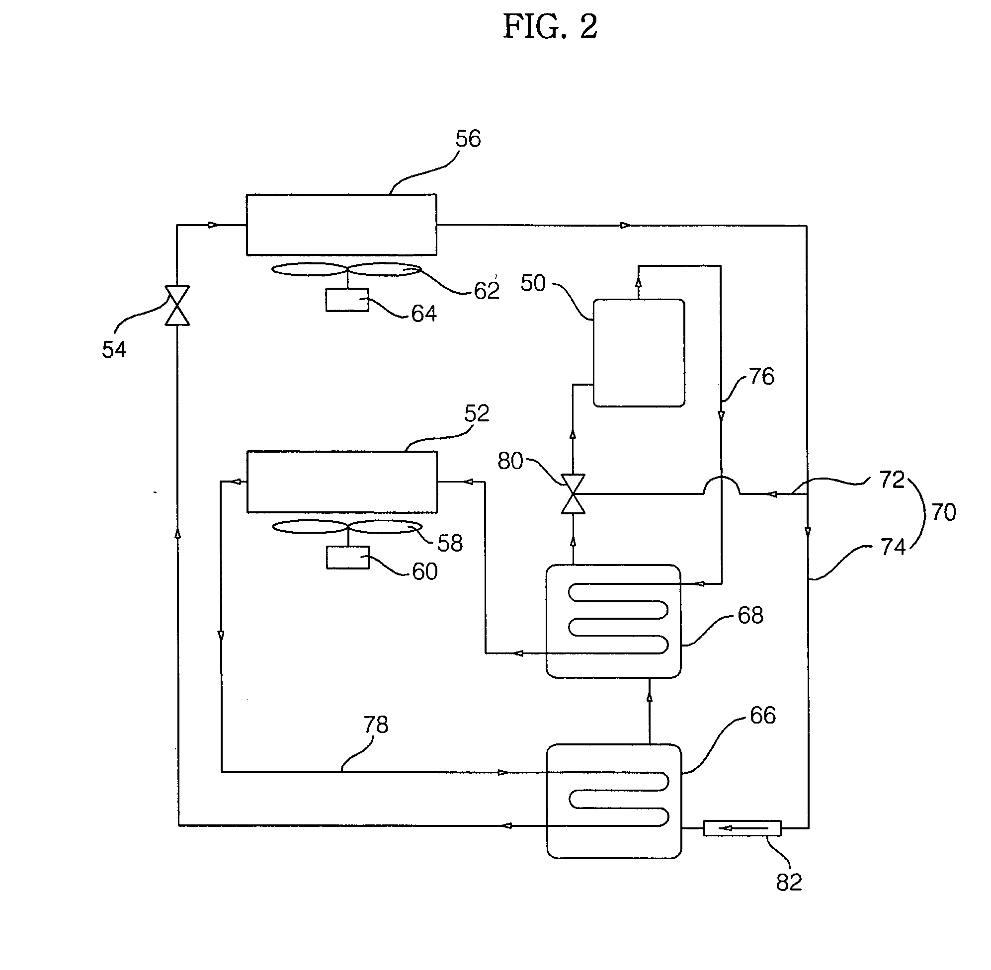
[0034]FIG. 2 is a schematic diagram illustrating a refrigerant cycle of an air conditioner according to the present invention.

[0035] As shown in FIG. 2, the air conditioner according to the first embodiment of the present invention includes a compressor 50 which compresses a refrigerant to a high-temperature and high-pressure gas state, a condenser 52 which condenses the refrigerant gas discharged out of the compressor 50 to a liquid state, an expansion device 54 which expands the refrigerant liquid emerging from the condenser 52, and an evaporator 56 which evaporates the refrigerant liquid emerging from the expansion device 54 to a gas state. The air conditioner also includes a pressurizer which is arranged between the evaporator 56 and the compressor 50, to raise the pressure of the refrigerant sucked into the compressor 50, namely, to pressurize the refrigerant, and an auxiliary condenser which is arranged between the compressor 50 and the condenser 52, to condense the refrigeran...

second embodiment

[0057]FIG. 3 is a schematic diagram illustrating a refrigerant cycle of an air conditioner according to the present invention.

[0058] As shown in FIG. 3, the air conditioner according to the second embodiment of the present invention includes compressors 90 which compress a refrigerant to a high-temperature and high-pressure gas state, a condenser 94 which condenses the refrigerant gas discharged out of the compressors 90 to a liquid state, an expansion device 96 which expands the refrigerant liquid emerging from the condenser 94, and an evaporator 98 which evaporates the refrigerant liquid emerging from the expansion device 96 to a gas state. The air conditioner also includes a pressurizer which is arranged between the evaporator 98 and the compressors 90, to raise the pressure of the refrigerant sucked into the compressors 90, namely, to pressurize the refrigerant, and an auxiliary condenser which is arranged between the compressors 90 and the condenser 94, to condense the refriger...


PUM


Abstract

An air conditioner is disclosed which includes a pressurizer for pressurizing a suction-side refrigerant sucked into a compressor, and an auxiliary condenser for condensing a discharge-side refrigerant discharged out of the compressor. Accordingly, it is possible to raise the evaporation pressure of the suction-side refrigerant sucked into the compressor, and to reduce the condensation pressure of the discharge-side refrigerant discharged out of the compressor. As a result, the difference between the suction and discharge pressures of the compressor can be reduced, so that a reduction in compression load can be achieved. Thus, a reduction in power consumption can be achieved.

Description

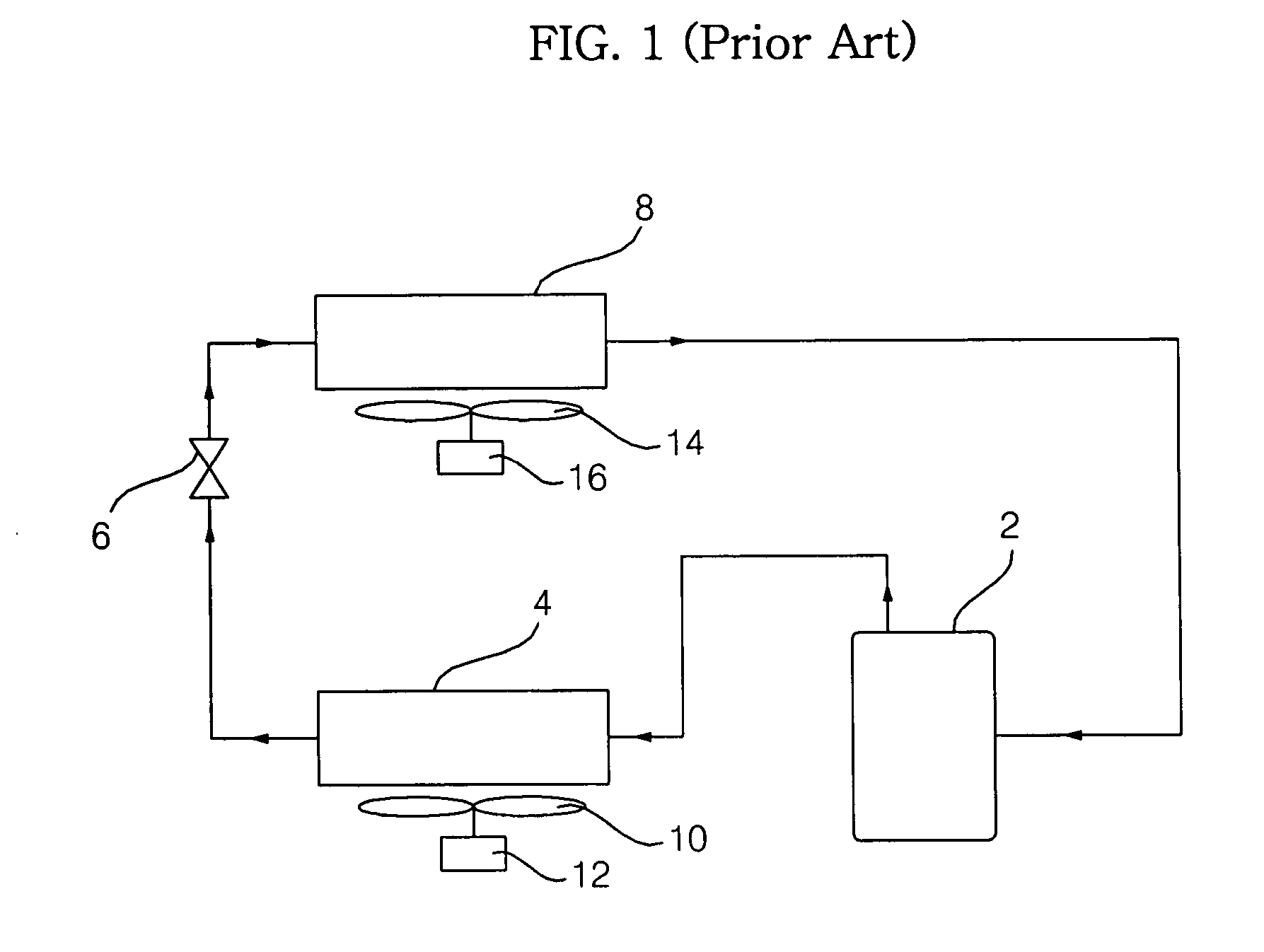
BACKGROUND OF THE INVENTION [0001] 1. Field of the Invention [0002] The present invention relates to an air conditioner, and, more particularly, to an air conditioner which is configured to reduce the difference between the suction and discharge pressures of a compressor included in the air conditioner, thereby being capable of achieving a reduction in power consumption, and thus, an enhancement in efficiency. [0003] 2. Description of the Related Art [0004] Generally, air conditioners are used to cool or heat an indoor space, in order to form more comfortable indoor environments. Such an air conditioner sucks indoor air from an indoor space, and then discharges the sucked indoor air into the indoor space after heating or cooling the indoor air. [0005]FIG. 1 is a schematic diagram illustrating a refrigerant cycle of a conventional air conditioner. [0006] As shown in FIG. 1, the conventional air conditioner includes a compressor 2 which compresses a low-temperature and low-pressure re...

Claims


Application Information

Patent Timeline
Patent Type & Authority Applications(United States)
IPC IPC(8): F25B41/00
CPCF25B6/04F25B40/00F25B40/06F25B41/04F25B2400/075F25B2600/2501F25B1/00F25B41/00
Inventor KIM, CHEOL MINHWANG, YOON JEI
Owner LG ELECTRONICS INC
Learn More