Centrifugal generator of a thrust force for aviation and space apparatuses

a technology of centrifugal generator and thrust force, which is applied in the direction of machines/engines, cosmonautic vehicles, and gearboxes, which can solve the problems of reducing the thrust force with an increase in flight speed and flight height, power reduction, and increasing flight speed, so as to increase the efficiency of the centrifugal generator

Inactive Publication Date: 2006-06-15
TSEPENYUK MIKHAIL +2
View PDF4 Cites 16 Cited by
  • Summary
  • Abstract
  • Description
  • Claims
  • Application Information

AI Technical Summary

Benefits of technology

[0013] In accordance with a further feature of the present invention, the masses have a central part which is formed as an aer

Problems solved by technology

The propeller however has the disadvantage in lowering of a thrust force with an increase of a flight speed and flight height.
It however has however the disadvantage in reduction of power with an increase of a flight speed; low efficiency; necessity to provide fuel and oxidants during flights and maneuv

Method used


Image

  • Centrifugal generator of a thrust force for aviation and space apparatuses
  • Centrifugal generator of a thrust force for aviation and space apparatuses
  • Centrifugal generator of a thrust force for aviation and space apparatuses

Examples


Embodiment Construction

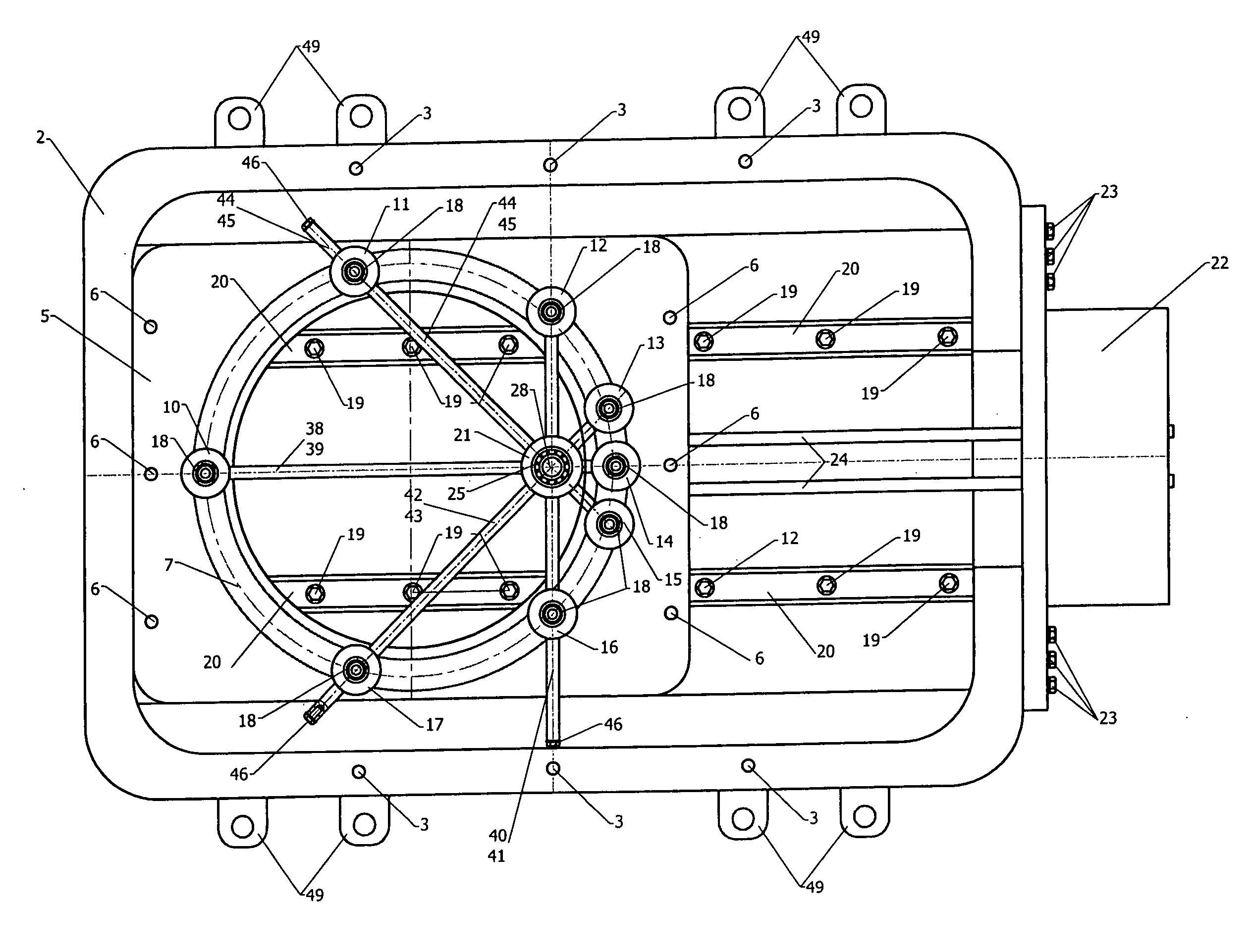
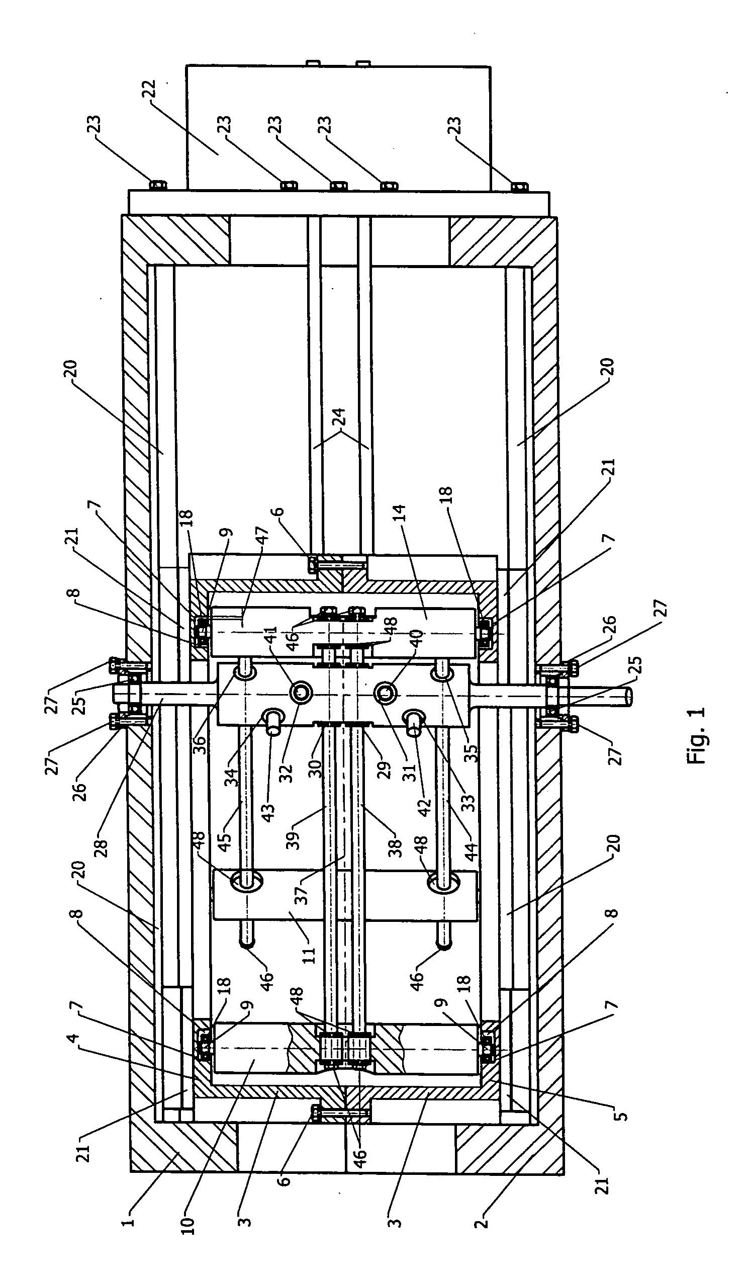
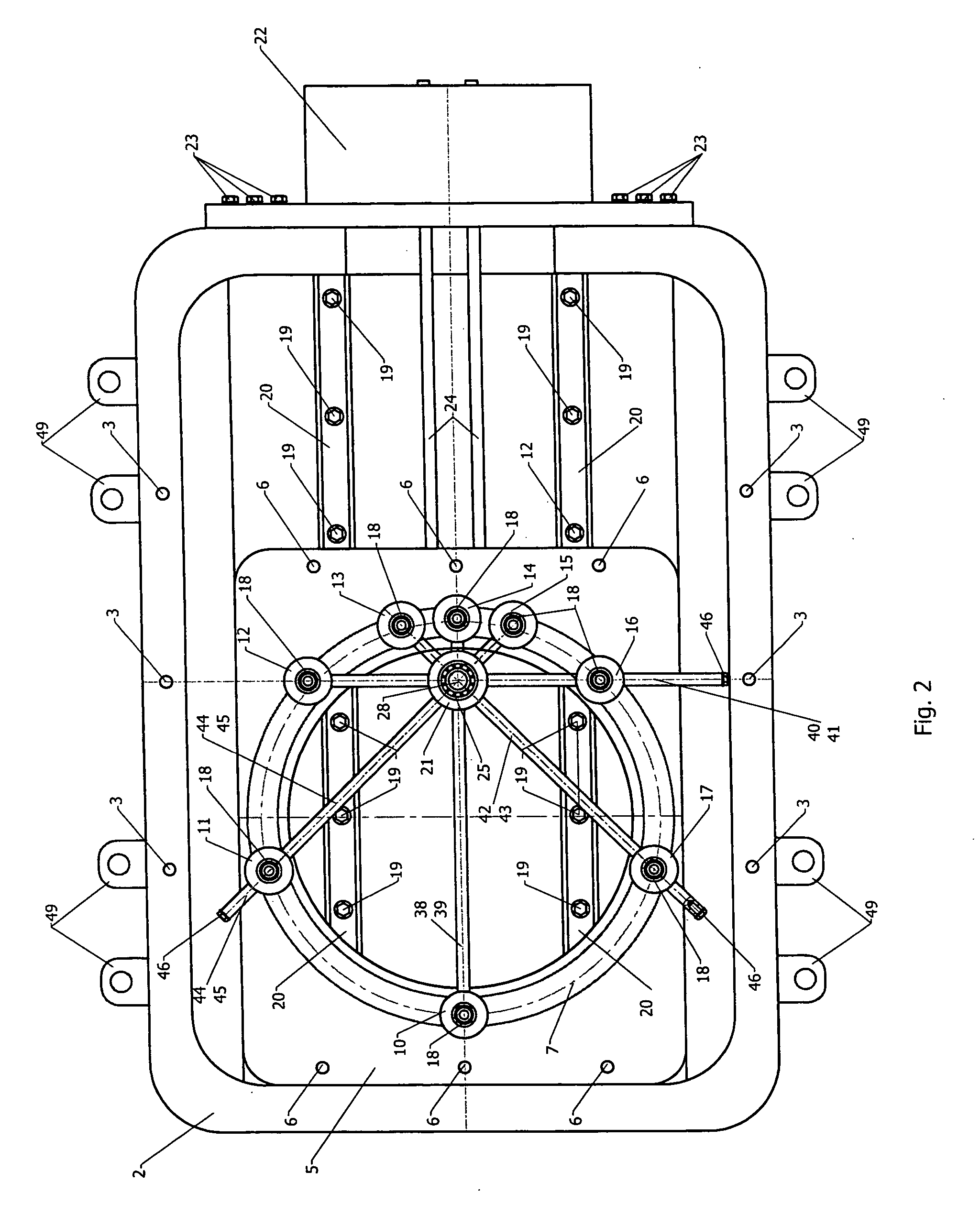
[0023] A centrifugal generator of a thrust force for flying apparatuses, such as an airplane, shown in FIGS. 1-4, is composed of a composite housing having two parts 1 and 2 connected by bolts 3 to form a single structure. It also includes an integrating element which is also composed of two parts 4 and 5 connected by bolts 6. Identical annular guides 7 are formed in the parts 4 and 5 of the integrating element as a grooves having a rectangular cross-section, which, with a gap 8 shown in FIG. 1, surround console parts 9 of work masses 10, 11, 12, 13, 14, 15, 16 and 17 together with roller bearings 18 arranged on the console parts 9.

[0024] Rails 20 are arranged on the inner surface of the parts 1 and 2 of the housing by means of bolts 19 shown in FIG. 2, and carriages 21 are arranged on the outer surfaces of the parts 4 and 5 of the integrating element. The carriages 21 and the rails 20 form parallel guides. A power mechanism 22 is arranged on the parts 1 and 2 of the housing and fi...


PUM


Abstract

A centrifugal generator of a thrust force for aviation and space application has a housing, an integrating element, work masses, a drive, the integrating element being composite and arranged in the housing with a possibility of a forced reciprocating displacement along parallel guides and has an annular guide formed by two identical annular grooves which surround console parts of the work mass with a clearance, the drive being formed as a lever-type drive with floating rods, that are provided with end stops with dampers and extending through an axis of a shaft and central parts of the work masses, the rods being arranged in pairs parallel to one another and in the pairs are located at a same distance from an axis of symmetry of the drive and arranged in pairs with a uniform angle of displacement, the rods interacting with the shaft and the work masses through sliding bearings, the rods having a length which provides a clearance of the console parts of the work masses when the console parts of opposite ones of the work masses are in contact in a position of a maximum distance from one another.

Description

BACKGROUND OF THE INVENTION [0001] The present invention relates to a construction of a device for generation of a thrust force, and in particular to a construction of a centrifugal generator of a thrust force for aviation and space apparatuses. [0002] A device of the above mentioned type which is a propeller is known in the art. It includes aerodynamic vanes which are located in a housing with a possibility of turning around a longitudinal axis and a power mechanism providing the turning. The propeller has been used in constructions of power sources of flying apparatuses for various purpose due to the simplicity of its construction, reliability and efficiency. The propeller however has the disadvantage in lowering of a thrust force with an increase of a flight speed and flight height. [0003] A jet engine method of obtaining a thrust force is also widely used in aviation and space apparatuses. Devices which provide obtaining of a jet or reactive thrust force include a diffusor (a na...

Claims


Application Information

Patent Timeline
IPC IPC(8): F16H27/04
CPCB64G1/409F03G3/00Y10T74/18536F16H33/20F03H99/00F03G7/10
Inventor TSEPENYUK, MIKHAILTSEPENYUK, DMITRYTSEPENYUK, IRENE
Owner TSEPENYUK MIKHAIL
Why Eureka
Try Eureka