Bypass for exhaust gas cooler

Active Publication Date: 2006-06-15
GARRETT TRANSPORATION I INC
View PDF6 Cites 34 Cited by
  • Summary
  • Abstract
  • Description
  • Claims
  • Application Information

AI Technical Summary

Benefits of technology

[0005] Thus an object of the present invention is to recirculate exhaust gas without over-cooling.
[0021] Preferably the bypass passage is enclosed in a housing. Preferably the housing is provided with a series of corrugations, typically to eliminate fatigue failure due to differential thermal expansion stress.

Problems solved by technology

However, under “cold start” or low operating conditions, the gas can be over-cooled resulting in increased hydrocarbon emission and CO2 production.

Method used


Image

  • Bypass for exhaust gas cooler
  • Bypass for exhaust gas cooler
  • Bypass for exhaust gas cooler

Examples


Embodiment Construction

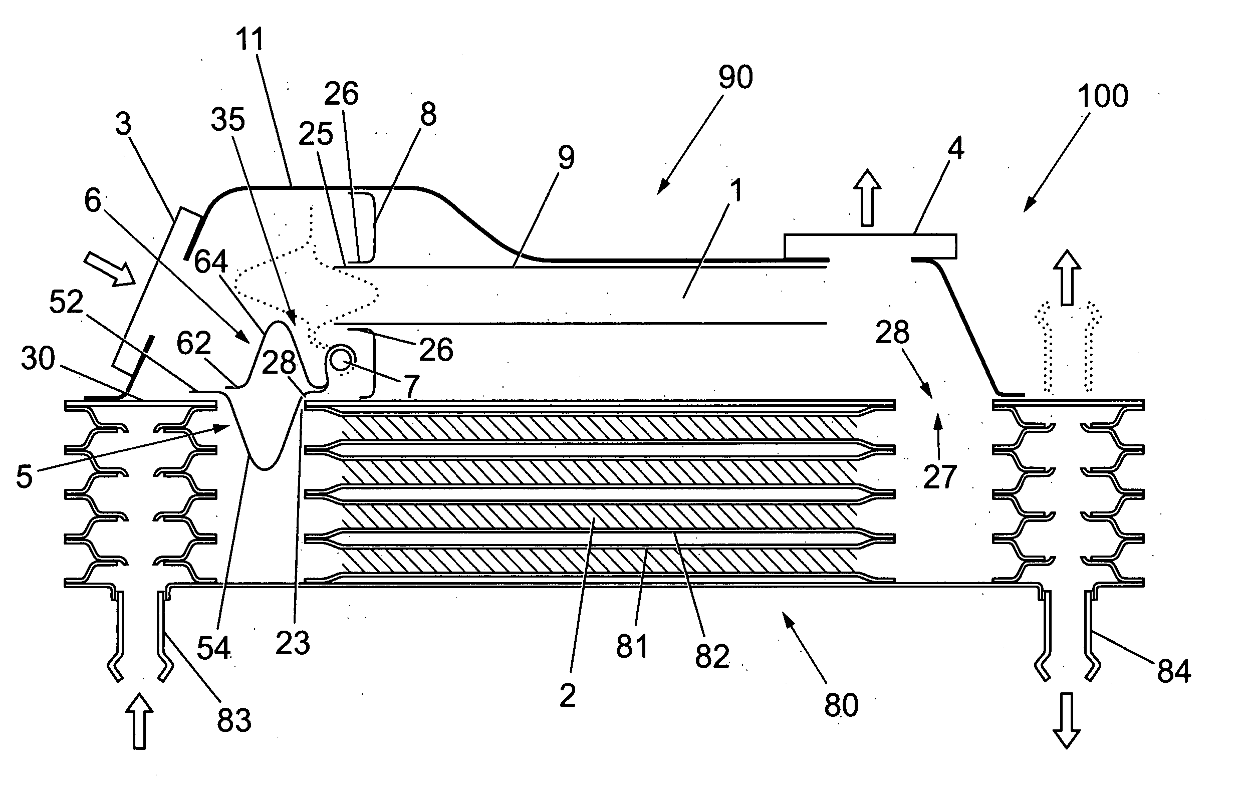
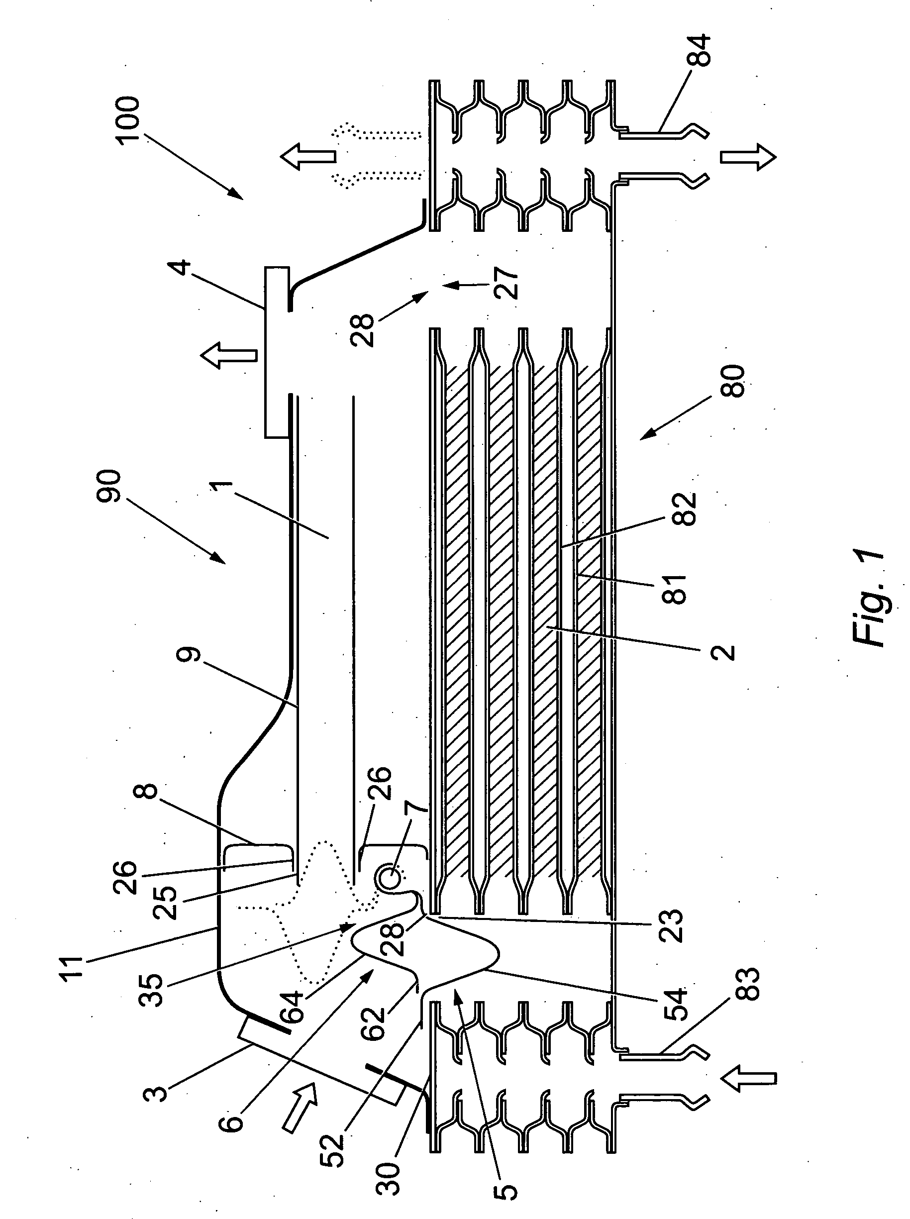
[0059] An exhaust gas cooler with bypass 100 is shown in FIGS. 1-3 and comprises an exhaust gas recirculation (EGR) cooler 80 and an attached bypass assembly 90.

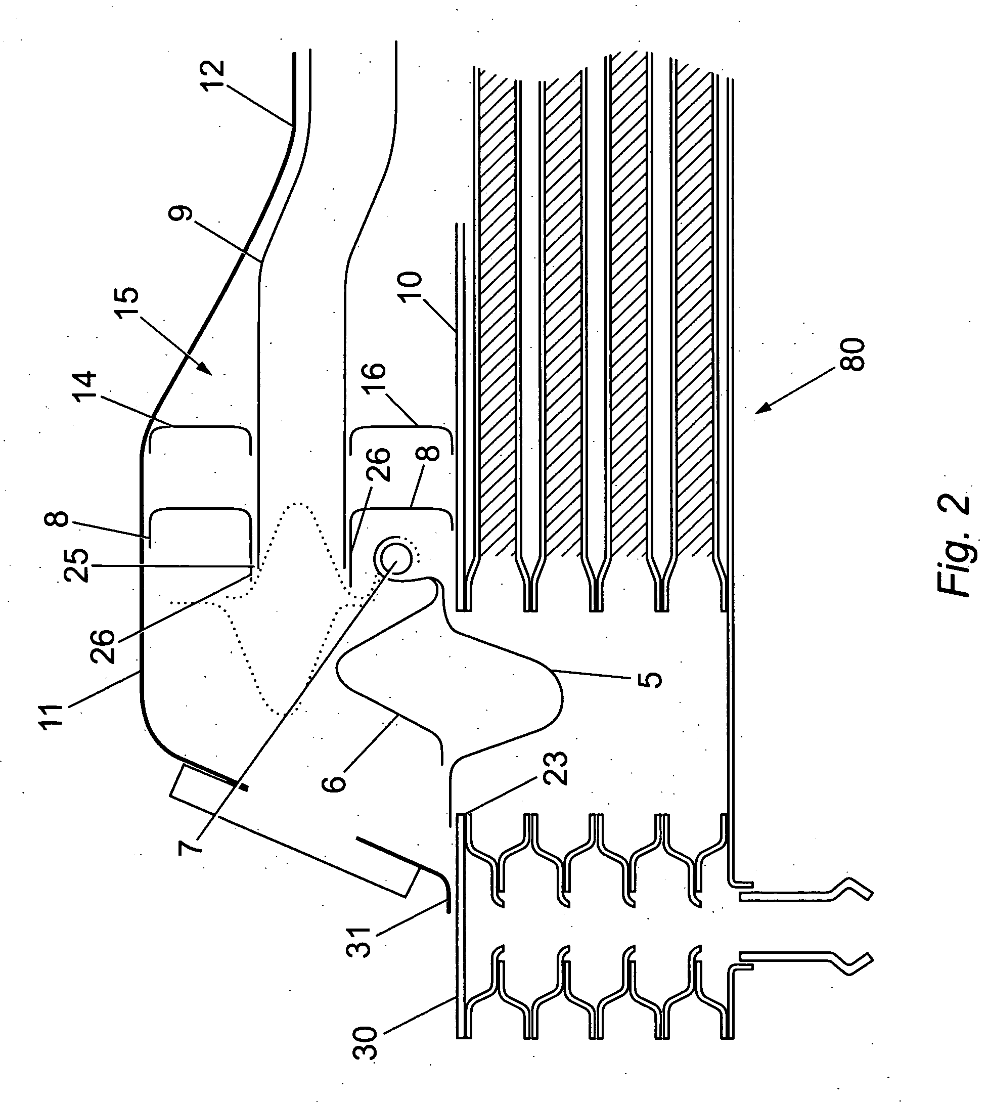
[0060] The bypass assembly 90 comprises a bypass housing 11 attached to the EGR cooler 80. The bypass housing 11 comprises an exhaust gas inlet 3, an exhaust gas outlet 4, a bypass tube 9, a sealing plate 8 and an open face 28 which interfaces with the EGR cooler 80.

[0061] The bypass seal 8 comprises a plate with an aperture 25 and seals the bypass housing 11 with the cooler 80, allowing exhaust gas to proceed only through the aperture 25 towards the outlet 4 or through open face 28 into the port 23 of the EGR cooler 80. The bypass seal 8 is welded to the housing 11 at one end but interfaces with the EGR cooler 80 by way of an interference fit and is preferably not welded thereto. This allows the bypass seal 8 to move slightly should the components expand and contract due to temperature variances.

[0062] The bypass tube 9 ...


PUM


Abstract

An exhaust gas recirculation cooler, typically of the drawn cup design, with a bypass and control valve is disclosed. The control valve can direct a proportion of the exhaust gas to the cooler and a proportion to bypass the cooler depending on the input temperature of the exhaust gas and the required temperature of the exhaust gas. The proportion of the exhaust gas directed to the cooler / bypassing the cooler can be varied as required and so the temperature of the exhaust gas can be controlled. One benefit of certain embodiments of the invention is that engine damaging chemicals, such as sulphuric acid, which result from over-cooling the exhaust gas are reduced.

Description

BACKGROUND OF THE INVENTION [0001] 1. Field of the Invention [0002] The present invention relates to a cooler for use in an exhaust gas recirculation (EGR) system in an internal combustion engine and particularly to a bypass around said cooler. [0003] 2. Description of the Related Art [0004] Emissions regulations are requiring reduced emissions from vehicles, particularly the Euro 5, Bin 5 and US 06 regulations. To reduce the generation of nitrous oxides, it is known to recirculate exhaust gas through the engine. Under normal conditions the exhaust gas must be cooled before recirculation and it is known to pass the exhaust gas through an exhaust gas cooler. However, under “cold start” or low operating conditions, the gas can be over-cooled resulting in increased hydrocarbon emission and CO2 production. SUMMARY OF THE INVENTION [0005] Thus an object of the present invention is to recirculate exhaust gas without over-cooling. [0006] According to a first aspect of the present invention...

Claims


Application Information

Patent Timeline
IPC IPC(8): F02M25/07F28F27/02
CPCF02M25/0729Y02T10/121F28D9/005F28F27/02F28F2250/06F02M26/26
Inventor SAYERS, JON A.REYMONDET, STEPHANELEMON, ANGUSSMITH, WILLI J.
Owner GARRETT TRANSPORATION I INC
Why Eureka
Try Eureka