Composite coating for die-casting mold and preparation method thereof
What is AI technical title?
AI technical title is built by Patsnap AI team. It summarizes the technical point description of the patent document.
A technology of composite coating and die-casting mold, which is applied in the direction of coating, metal material coating process, vacuum evaporation plating, etc., to achieve good surface hardness, improve service life and reduce mold deformation
Active Publication Date: 2020-03-17
INST OF MECHANICS CHINESE ACAD OF SCI +1
View PDF6 Cites 0 Cited by
Summary
Abstract
Description
Claims
Application Information
AI Technical Summary
This helps you quickly interpret patents by identifying the three key elements:
Problems solved by technology
Method used
Benefits of technology
Problems solved by technology
[0005] However, it is difficult for this type of coating to meet the requirements of hardness, wear resistance, and life of mold products at the same time. There are still many technical difficulties in improving the service life of die-casting molds in large-scale production, mainly including improving the body strength and toughness of the coating. , improve the lubricity of the coating, and improve the bonding force between the hard film layer and the substrate, etc.
Method used
Image
Click on the blue label to locate the original text in one second.
Reading with bidirectional positioning of images and text.
Examples
Embodiment 1
[0065] by H 13 The working surface of the die-casting mold base made of die steel material is polished, and the mold base is degreased, dewaxed, cleaned and dried by ultrasonic cleaning.
[0066] Place the cleaned and dried mold base in the cavity of the vacuum cathodeion plating equipment, heat to 400 degrees, and vacuumize to 5×10 -3 Pa, feed Ar to maintain the air pressure at 1.2Pa, turn on the ion source of the anode layer, the current is 3A, the substrate holder rotates at 1rpm, the negative bias is -900V, and the bombardment time is 60min.
[0067] After glow cleaning, the vacuum was adjusted to 0.8Pa, the metal Cr target was turned on, the bias voltage was kept at -300V, the current was 75A, and it was deposited for 10min to obtain a Cr metalinterface bonding layer with a thickness of 120nm.
[0068] After depositing the Cr binding layer, the bias voltage is reduced to -150V, and the N 2 , control the air pressure at 0.8Pa, the substrate temperature at 400°C, the du...
Embodiment 2
[0074] The surface of the die-casting mold made of Y10 material is polished, and the mold base is degreased, dewaxed, cleaned and dried by ultrasonic cleaning.
[0075] Place the cleaned and dried mold base in the cavity of the vacuum cathodeion plating equipment, heat to 500°C, evacuate to 5×10⁻³Pa, and inject Ar gas to maintain the air pressure at 1.2Pa. Turn on the ion source of the anode layer, the current is 3A, the rotation speed of the substrate holder is 1rpm, the negative biasvoltage is -900V, and the bombardment time is 60min.
[0076] After glow cleaning, the vacuum was adjusted to 0.9Pa, the metal Cr target was turned on, the bias voltage was kept at -300V, the current was 80A, and the deposition time was 10min to obtain a Cr metal interface bonding layer with a thickness of 180nm.
[0077]After depositing the Cr binding layer, the bias voltage is reduced to -150V, and the N 2 , control the air pressure at 0.8Pa, the substrate temperature at 450°C, the duty cycl...
PUM
Property
Measurement
Unit
thickness
aaaaa
aaaaa
thickness
aaaaa
aaaaa
thickness
aaaaa
aaaaa
Abstract
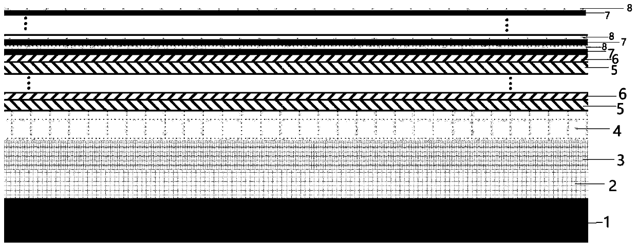
The invention provides a high-temperature-resistant self-lubricating high-hardness and high-toughness gradient composite coating suitable for a die-casting die and a preparation method thereof. The hcomposite coating is composed of a bonding layer, a transition layer, a supporting layer and a functional layer which are arranged on a die base body in a deposited mode and are sequentially stacked from inside to outside; the bonding layer is a Cr bonding layer for improving the bonding force between the composite coating and the surface of the die; the transition layer is formed by compounding aCrN transition layer and a CrA1N transition layer; the supporting layer is formed by alternately overlapping and compounding a CrA1SiN layer and a CrA1VN layer; and the functional layer is formed byalternately overlapping and compounding a CrA1SiCN layer and a CrA1VCN layer. The composite coating is good in surface hardness, wear resistance, high-temperature oxidation resistance and corrosion resistance, and good in self-lubricating effect, can remarkably reduce the shape change of the die, improves the die precision, eliminates the fatigue failure of the die coating, prolongs the service life, and is suitable for the development of a complex modeling die.
Description
technical field [0001] The invention relates to the technical field of preparation of coatings and die-casting molds, in particular to a high-temperature-resistant self-lubricating gradient composite coating with high hardness and toughness suitable for die-casting molds and a preparation method for depositing the gradient composite coating. Background technique [0002] Die-casting molds are a large category of molds. In today's era of rapid industrial development, die-casting molds have ushered in new vitality along with the development of the automobile industry, but at the same time they have also ushered in new challenges. Large complex-shaped die-casting molds are prone to deformation when they need to directly contact high-temperature molten metal. At present, it is still necessary to improve the efficiency, precision and life of such molds. [0003] The main problems faced by die-casting molds include the following points: the working environment is high temperature,...
Claims
Application Information
Patent Timeline
Application Date:The date an application was filed.
Publication Date:The date a patent or application was officially published.
First Publication Date:The earliest publication date of a patent with the same application number.
Issue Date:Publication date of the patent grant document.
PCT Entry Date:The Entry date of PCT National Phase.
Estimated Expiry Date:The statutory expiry date of a patent right according to the Patent Law, and it is the longest term of protection that the patent right can achieve without the termination of the patent right due to other reasons(Term extension factor has been taken into account ).
Invalid Date:Actual expiry date is based on effective date or publication date of legal transaction data of invalid patent.

