
Vibration isolator and attachment method thereof

a technology of vibration isolator and isolator body, which is applied in the direction of machine supports, transportation and packaging, etc., can solve the problems of generating unusual noises such as squeaking noises, preventing the generation of strange noises, and maintaining the vibration isolating characteristics. , to achieve the effect of maintaining the adhesion state further more satisfactorily, preventing the generation of strange noises, and satisfying the maintenance of steering stability

Active Publication Date: 2006-06-15
TOYO TIRE & RUBBER CO LTD
View PDF6 Cites 37 Cited by
  • Summary
  • Abstract
  • Description
  • Claims
  • Application Information

AI Technical Summary

Benefits of technology

[0016] The present invention has been made in view of the problems described above, and is designed to adhere a bushing main body made of rubber elastomer to a bar member, e.g., a stabilizer bar thereby preventing generation of strange sounds due to the slip and to improve on the steering stability by. More particularly, the invention will provide a vibration isolator and attachment method thereof that are capable of ensuring a predetermined contact pressure over the whole peripheral surface of a bore of the bushing main body thereby securing the adhesion and in the state of use, are capable of imparting a certain degree of compression amount to the bushing main body so as to elevate the durability. MEANS OF SOLUTION OF THE PROBLEMS

Problems solved by technology

With such a bushing main body as stated above that is fixed to the bar member by compressive force (friction force), however, because of non-adhesive bonding a problem existed in that for example, when used for an automotive stabilizer bar, a slipping between the bar member and the bushing main body occurs owing to swaying or torsional movement of the bar member caused by abrupt starting or stopping, or turning, etc. of a vehicle, as a result of which unusual noises such as a squeaking noise are generated.
In particular, also where the attachment state or fastening state to the car body or the bar member is devised so as to make the compression amount large to increase the friction force, as is the case with Patent References 1 and 2 listed below, because of non-adhesive anchoring, a strange noise due to the slipping was seldom, if ever generated in a low temperature situation or upon ingress of water and besides, a preventive effect against positional slippage (shifting) in the axial direction was not sufficient either, and there was a problem in the retention of vibration isolating characteristics.
However, the problems with this case were that due to easy sliding between the bushing main body and the bar member, that approach is disadvantageous in the respect of the preventive effect to lateral sliding or detachment and consequently, it is necessary to conjointly use any preventive means against detachment and besides, because of good sliding, the steering stability is impaired.
In either case, a heating treatment step is necessitated and additionally, the bushing main body itself made of rubber elastomer is heated upon adhering, as a result of which there is a danger of change in characteristics thereof.
Nevertheless if the rubber elastomer is adhered in an excessively compressed state, a high temperature heat of 160 to 180° C. will be generated at the adhered area, so that the problem arises that the characteristics of the rubber elastomer are changed, accelerating a degradation of rubber.

Method used


Image

  • Vibration isolator and attachment method thereof
  • Vibration isolator and attachment method thereof
  • Vibration isolator and attachment method thereof

Examples


Embodiment Construction

[0028] The embodiments of the invention will be hereinafter described with reference to examples shown in the accompanying drawings.

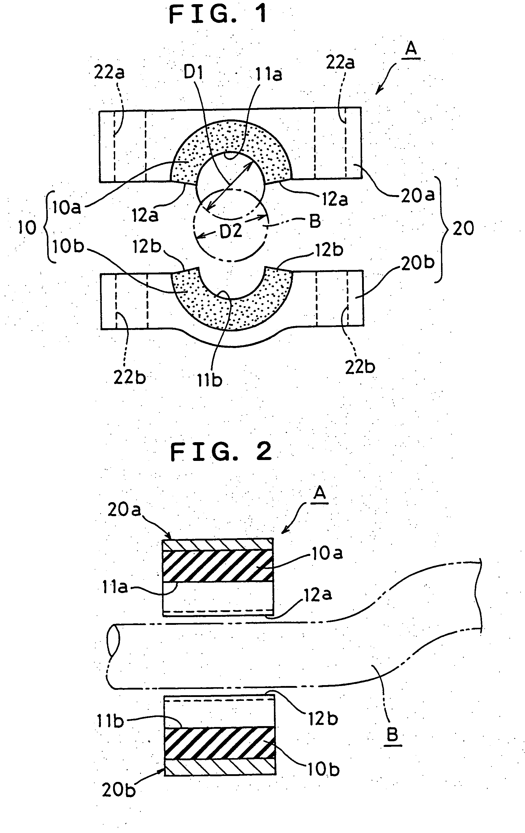
[0029]FIG. 1 is a front elevation of a vibration isolator of this invention showing a separated state prior to its attachment to a bar member;

[0030]FIG. 2 is a longitudinal sectional view of FIG. 1;

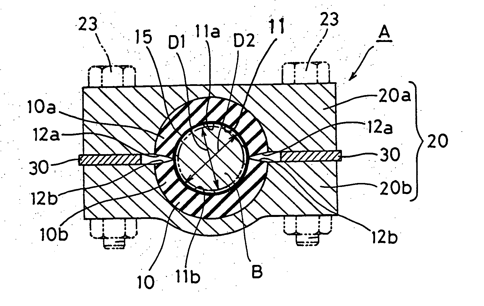
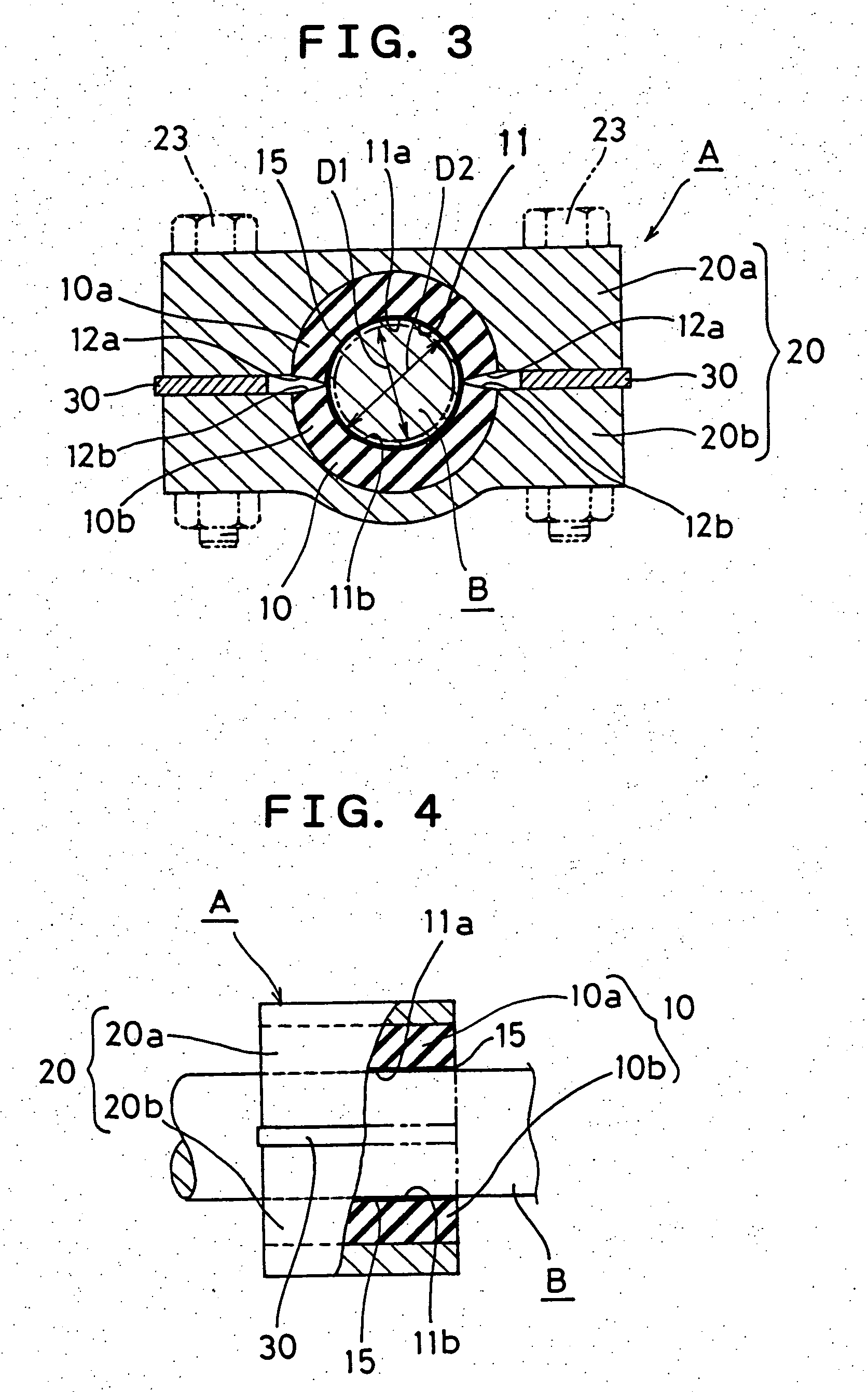
[0031]FIG. 3 is a sectional view of the vibration isolator in FIG. 1 upon adhering to the bar member;

[0032]FIG. 4 is a side elevational view in partial cross-section of the vibration isolator in FIG. 3 in the adhered state; and

[0033]FIG. 5 is a sectional view similar to FIG. 3, but showing the state that half bracket members are completely locked together.

[0034] The illustrated example shows a case of the vibration isolator A used as a stabilizer bushing. The vibration isolator A includes a bushing main body 10 made of rubber elastomer assuming a thick-walled cylinder shape and having a bore 11 through which a bar member B as a stabilizer bar passes, and ...


PUM

PropertyMeasurementUnit
Thicknessaaaaaaaaaa
Diameteraaaaaaaaaa

Abstract

The invention is to permit a bushing main body of rubber elastomer to be adhered to a bar member while retaining a necessary contact pressure for adhering and after adhering, to permit a further compressive force to be imparted. The bushing main body (10) having a bore (11), through which the bar member (B) passes, and a bracket (20) holding the former are longitudinally split into two, respectively, the resulting split rubber bodies (10a)(10b) are vulcanization bonded to inner peripheral surfaces of the resulting half bracket members (20a)(20b). The inside diameter (D1) of both split rubber bodies as molded is made smaller than the outside diameter (D2) of the bar member, and inner peripheral surfaces (11a)(11b) at the bore are formed to be eccentric on mutually opposite sides. While pinching the bar member by both split rubber bodies, both half bracket members interposing a spacer (30) are locked together to compress the split rubber bodies thereby to adhere the peripheral surfaces at the bore to the outer peripheral surface of the bar member, and after the spacer is removed, both half members are locked so as to butt contact with each other thereby further compressing both split rubber bodies in mutually opposing directions.

Description

TECHNICAL FIELD [0001] This invention relates to a vibration isolator assembly used as a stabilizer bushing, a rear suspension bushing or other various rubber bushings for automotive vehicles and its attachment method. BACKGROUND ART [0002] Rubber bushings, e.g., a stabilizer bushing, rear suspension bushing, etc. which are a kind of automotive vibration isolating device are generally formed of a rubber elastomer assuming a thick-walled cylinder shape and used in the state that a bar member such as a stabilizer bar for vehicles is inserted through its bore and held in place. [0003] A vibration isolator assembly formed of such a rubber bushing comprises a thick-walled cylindrical bushing main body made of rubber elastomer having a bore through which a bar member such as a stabilizer bar passes, and a bracket holding the bushing main body from outwardly thereof. For example, the bracket consists of a pair of bracket members formed by splitting thereof into an attachment side to be att...

Claims


Application Information

Patent Timeline
IPC IPC(8): F16F1/44
CPCB60G21/0551B60G2202/135B60G2204/1222B60G2204/41F16F1/3732F16F1/38B29L2031/04B29L2031/721B29C66/1122B29C66/1142B29C66/532B29C66/71B29C66/742B29C66/83221B29C66/92655B29L2031/3055B29C65/48B29K2021/00B29C65/4835B29C65/4865
Inventor NIWA, SATOSHINISHIYAMA, KAZUSHIMASUDA, HIROYUKITERANISHI, YASUHIRO
Owner TOYO TIRE & RUBBER CO LTD
Learn More