Lighting control circuit for vehicle lighting device

Inactive Publication Date: 2006-06-15
KOITO MFG CO LTD
View PDF5 Cites 25 Cited by
  • Summary
  • Abstract
  • Description
  • Claims
  • Application Information

AI Technical Summary

Benefits of technology

[0007] The present invention has been made in light of the above problem and, in some implementations, the present invention

Problems solved by technology

Even if the vehicle lighting device is designed in view of the fact that the peak value of the primary current I1 is increased, respective capacities of the main switch SW (sw

Method used


Image

  • Lighting control circuit for vehicle lighting device
  • Lighting control circuit for vehicle lighting device
  • Lighting control circuit for vehicle lighting device

Examples


Embodiment Construction

[0028] Below, an implementation of the present invention is explained.

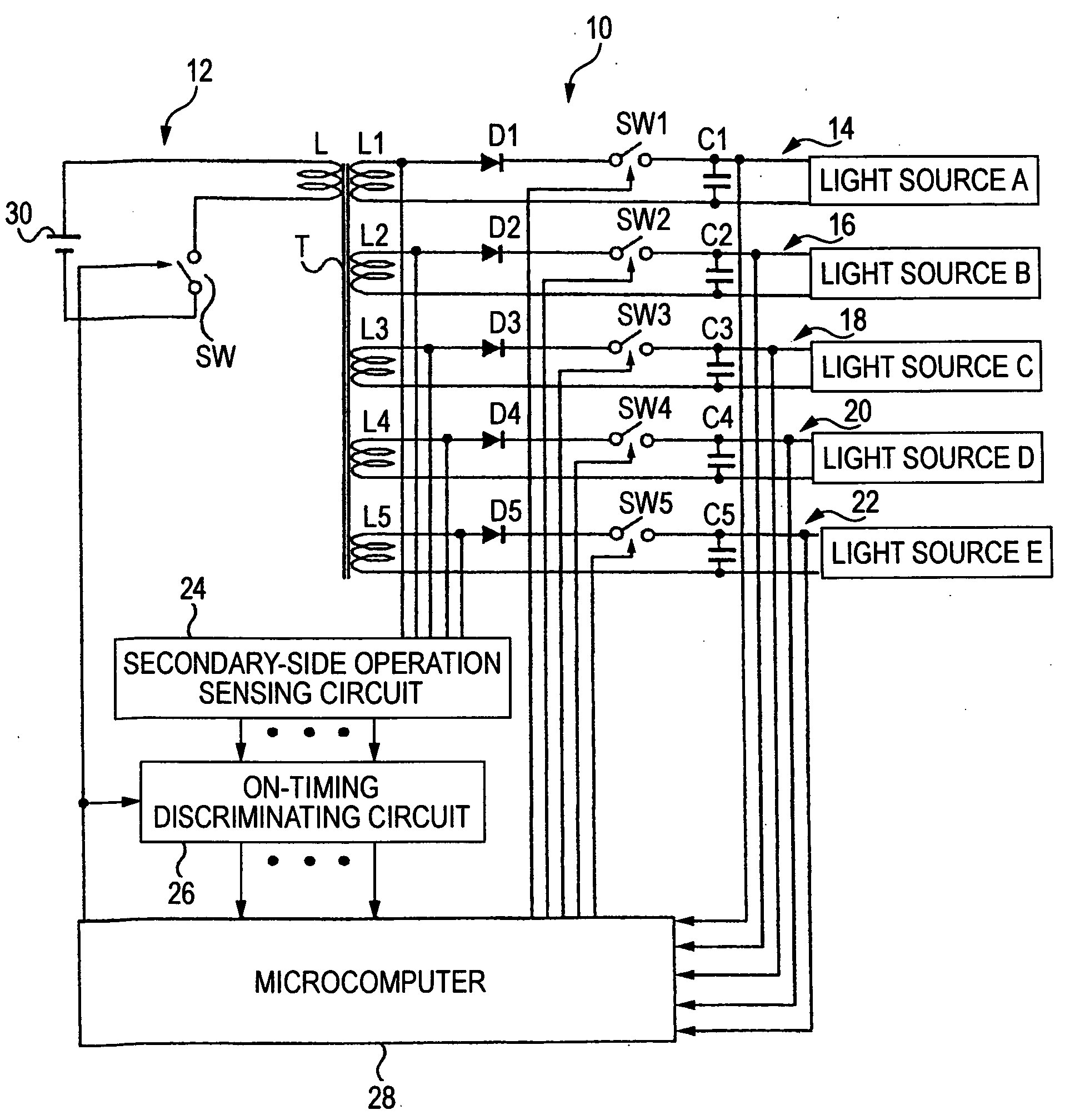
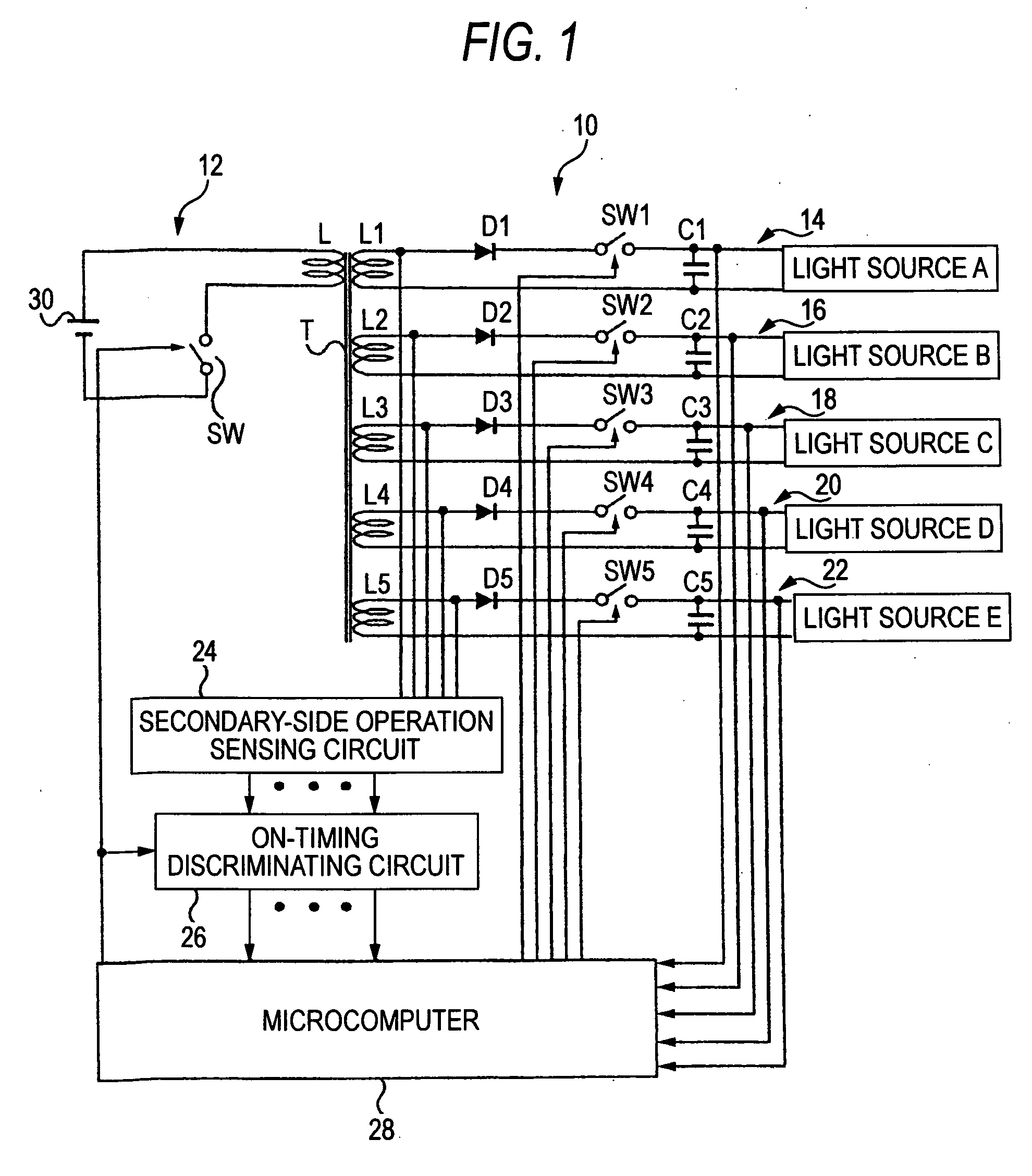
[0029] As illustrated in the figures, a lighting control circuit 10 for a vehicle lighting device includes a multi-output type switching regulator 12, output blocks 14, 16, 18, 20, 22, a secondary-side operation sensing circuit 24, an ON-timing discriminating circuit 26, and a microcomputer 28 (referred to as a “micro” hereinafter) as an element of the vehicle lighting device (light emitting device) respectively to energize five semiconductor light sources A, B, C, D, E. The semiconductor light sources A to E may comprise LEDs, for example, as the semiconductor light emitting elements.

[0030] A single LED can be employed as the light emitting element. Alternatively, two or more series-connected LEDs may be employed. In other implementations, parallel-connected light source blocks, each of which may be constructed by connecting LEDs in series, may be employed. Also, respective semiconductor light sources A to E ca...


PUM


Abstract

An ON/OFF-operation of a main switch SW and auxiliary switches SW1 to SW5 is controlled by a microcomputer 28. Electromagnetic energy in a transformer T is accumulated in an ON operation of the main switch SW and discharged in the transformer T sequentially to output blocks 14 to 22 on the secondary side in an OFF operation of the main switch SW. The electromagnetic energy is discharged twice separately to the output blocks 14, 18 connected to semiconductor light sources A, C having a heavy load, respectively, in one control period T, whereas the electromagnetic energy is discharged only once to the output blocks 16, 20, 22 connected to remaining semiconductor light sources B, D, E, respectively. Therefore, the peak value of the primary current I1 flowing through the primary winding L of the transformer T can be reduced.

Description

TECHNICAL FIELD [0001] The present disclosure relates to a lighting control circuit for a vehicle lighting device and, more particularly, to a lighting control circuit for a vehicle lighting device constructed to control the lighting state of a semiconductor light source composed of a semiconductor light emitting element. BACKGROUND ART [0002] An LED (Light Emitting Diode) is an example of a semiconductor light source that has been used in vehicle lighting devices. A lighting control circuit to control the lighting state of the LED is installed into the vehicle lighting device of this type. [0003] The lighting control circuit may include a switching regulator that includes a switching element and a transformer, and also an output block that includes a rectifier diode and a smoothing capacitor to operate such that an input voltage: fed from a DC power supply is accumulated in the transformer as an electromagnetic energy when the switching element is turned ON. The electromagnetic ene...

Claims


Application Information

Patent Timeline
IPC IPC(8): H02G3/00
CPCH05B33/0815H05B33/0818Y02B20/346Y02B20/30H05B45/3725
Inventor NAMBA, TAKANORIITO, MASAYASU
Owner KOITO MFG CO LTD
Why Eureka
Try Eureka