Projection optical system, magnification projection optical system, magnification projection apparatus, and image projection apparatus
a projection optical system and magnification projection technology, applied in the field of projection optical systems, can solve the problems of chromatic aberration generation, imaging optical systems composed of only reflecting surfaces cannot correct chromatic aberration, and so on
- Summary
- Abstract
- Description
- Claims
- Application Information
AI Technical Summary
Benefits of technology
Problems solved by technology
Method used
Image
Examples
embodiment 1
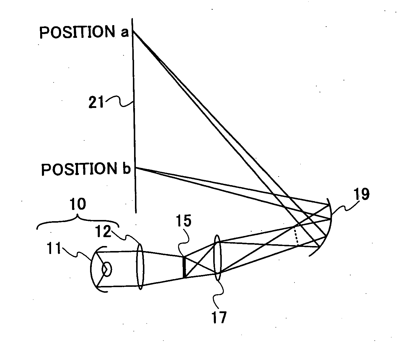
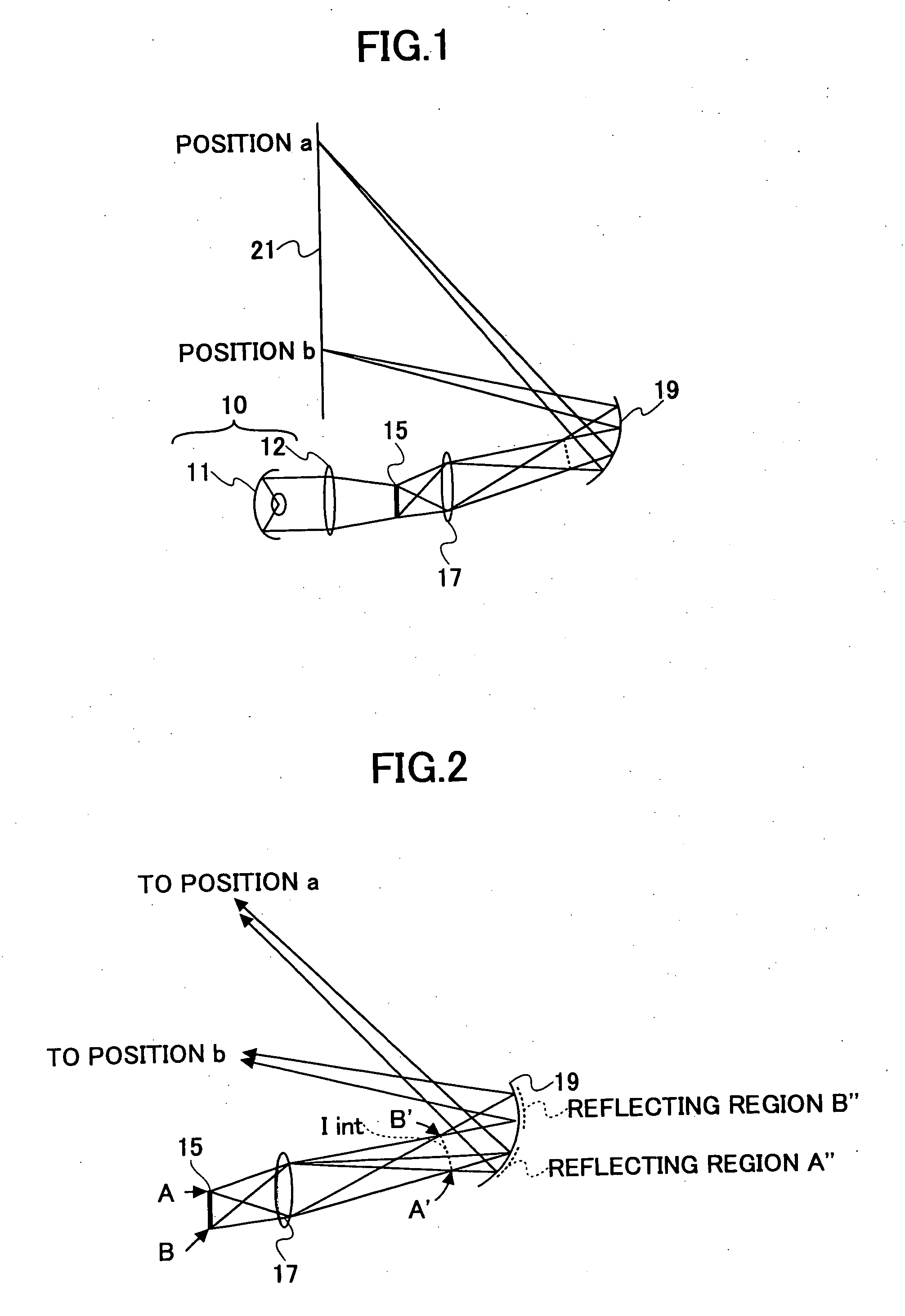
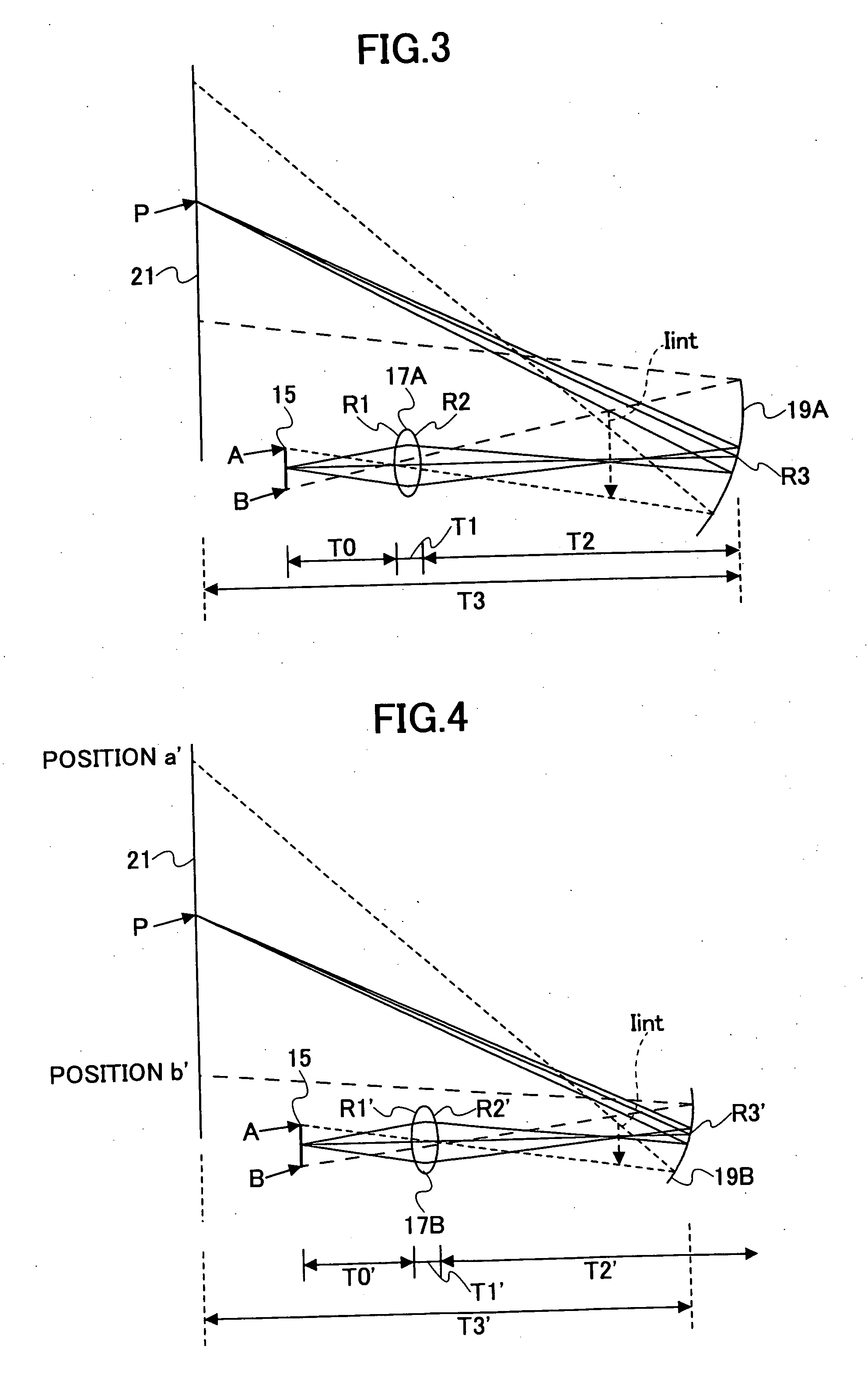
[0205] Embodiment 1 is a specific embodiment of the image projection apparatus and the projection optical system of FIGS. 7 and 8. That is, Embodiment 1 includes the first optical system 71 having positive power and including at least one dioptric system and the second optical system 72 including at least one reflecting surface having power and having positive power as a whole. The first and second optical systems 71 and 72 are arranged in the order described from upstream to downstream on the downstream side of the object surface. An object image is temporarily formed as an intermediate image, and thereafter, is formed as a normal image. The optical elements 712 through 716, 721, and 722 are shifted or tilted with respect to the optical axis of the optical element 711 having refractive power, which is positioned at the furthest upstream end of the first optical system 71.
[0206] The magnification of the intermediate image is approximately 3×.
[0207] The data of Embodiment 1 is show...
embodiment 2
[0215] Embodiment 2 is a specific embodiment of an image projection apparatus and a projection optical system shown in FIG. 12. In FIG. 12, the projection optical system of the image projection apparatus is shown enlarged.
[0216] The projection optical system includes a first optical system 81 and a second optical system 82. The first optical system 81 is composed of six lenses 811 through 816. The second optical system 82 is composed of two reflecting surfaces 821 and 822. A diaphragm (not graphically represented) is provided between the lenses 813 and 814.
[0217] Like in Embodiment 1, an intermediate image is formed as an inverted image by the first optical system 81 between the reflecting surfaces 821 and 822. The reflecting surface 821, which has positive power and reflects a light beam made incident on the second optical system 82 first, has a rotationally symmetric aspheric figure. The reflecting surface 822 is a polynomial free-form surface. In Embodiment 2, the employment of...
embodiment 3
[0222] Embodiment 3 is a specific embodiment of an image projection apparatus and a projection optical system shown in FIG. 13.
[0223] The projection optical system includes a first optical system 91 and a second optical system 92. The first optical system 91 is composed of five lenses 911 through 915. The second optical system 92 is formed of two reflecting surfaces 921 and 922. The lens 913 is a doublet. A diaphragm (not graphically represented) is provided between the lenses 913 and 914.
[0224] Like in Embodiments 1 and 2, an intermediate image is formed between the reflecting surfaces 921 and 922. The intermediate image is formed as an inverted image by the first optical system 91. The reflecting surface 921, which has positive power and reflects a light beam made incident on the second optical system 92 first, has a spherical figure. The reflecting surface 922 is a polynomial free-form surface.
[0225] The data of Embodiment 3 is shown in Table 6.
TABLE 6SurfaceRadius ofSurface...
PUM
 Abstract
Description
Claims
Application Information
 - R&D
- Intellectual Property
- Life Sciences
- Materials
- Tech Scout
- Unparalleled Data Quality
- Higher Quality Content
- 60% Fewer Hallucinations
Browse by: Latest US Patents, China's latest patents, Technical Efficacy Thesaurus, Application Domain, Technology Topic, Popular Technical Reports.
© 2025 PatSnap. All rights reserved.Legal|Privacy policy|Modern Slavery Act Transparency Statement|Sitemap|About US| Contact US: help@patsnap.com


