Artificial tooth root implantation position determining instrument, artificial tooth root implantation position determining method, guide member manufacturing device, sensor, drill, artificial tooth manufacturing device, computer program, and recorded medium

a technology of artificial tooth root and position determination, which is applied in the field of artificial tooth root implantation position determination, can solve the problems of difficult to see dentition, difficult to obtain a three-dimensional grasp of tooth and jaw bone, and extremely difficult to bore an artificial tooth root cavity, etc., and achieves improved image quality, greater anatomical safety, and improved mechanical stability.

Inactive Publication Date: 2006-06-15
CAT CORP
View PDF2 Cites 100 Cited by
  • Summary
  • Abstract
  • Description
  • Claims
  • Application Information

AI Technical Summary

Benefits of technology

[0017] Furthermore, it is another object of the present invention to provide an artificial tooth root implantation position determining instrument which determine implantation positions that reduce the load on the jaw bone caused by masticating movement, this being accomplished by determining implantation positions with mechanical evaluation factors generated in the jaw bone in the vicinity of the position where the artificial tooth root is to be implanted being taken into account.
[0048] In cases where this invention is used, artificial tooth data and occlusion information created by the abovementioned artificial tooth root implantation position determining instrument are acquired, and an artificial tooth with an occlusion face indicated by this occlusion information and a shape indicated by the artificial tooth data is formed by planing, so that the artificial tooth data and occlusion information obtained can be utilized in the calculation of an appropriate artificial tooth root implantation position, thus making it possible to manufacture with good precision an artificial tooth that conforms to the occlusion operation and mastication movement.

Problems solved by technology

Here, the dental physician predicts the position in which the artificial tooth root is to be implanted from the direction of the opaque stopping of the diagnostic stent and the cross-sectional image of the jaw bone on the CT film; however, in cases where the direction of the opaque stopping of the diagnostic stent is inappropriate, the surgical treatment stent must be repaired using the intuition and experience of the dental physician.
Furthermore, since the CT film is a two-dimensional image, it is difficult to obtain a three-dimensional grasp of the tooth and jaw bone.
For example, there is a thick nervous system called the lower jaw channel in the lower jaw bone, and there is a cavity called the upper jaw cavity in the upper jaw; furthermore, tooth roots of the adjacent remaining teeth are present in the vicinity of the lost portion where the artificial tooth root is to be implanted, and it is extremely difficult to bore an artificial tooth root cavity while avoiding such nervous systems, cavities, tooth roots of remaining teeth and the like.
However, for example, in cases where the patient has an existing metal cap on a tooth that has already been treated, the X-ray beam during CT imaging is reflected by this cap, so that artifacts are generated in the CT data that is acquired, and the image quality of the dentition areas in particular deteriorates so that this dentition is difficult to see; as a result, it is difficult for the dental physician to predict an appropriate artificial tooth root implantation position.
Furthermore, in the artificial tooth root cavity boring procedure using the abovementioned method, although it is possible to bore an artificial tooth root cavity in an anatomically safe position, absolutely no consideration is given to mechanical evaluation factors generated in the nearby jaw bone by the stress received from the opposing tooth during masticating movement and the like.
Furthermore, it is relatively difficult to securely stabilize the auxiliary member that aids in the abovementioned artificial tooth root cavity boring procedure inside the oral cavity; in addition, even in cases where a boring procedure is performed utilizing a stabilized auxiliary member, since the boring procedure is performed by the dental physician, it is difficult to securely prevent human error.
Moreover, in the abovementioned method, a dental technician must form the final artificial tooth shape on the basis of a dentition pattern mold of the patient prepared by the dental physician; accordingly, skill, time and cost are required for the preparation of the dentition pattern mold and the formation of the artificial tooth by the dental technician.

Method used


Image

  • Artificial tooth root implantation position determining instrument, artificial tooth root implantation position determining method, guide member manufacturing device, sensor, drill, artificial tooth manufacturing device, computer program, and recorded medium
  • Artificial tooth root implantation position determining instrument, artificial tooth root implantation position determining method, guide member manufacturing device, sensor, drill, artificial tooth manufacturing device, computer program, and recorded medium
  • Artificial tooth root implantation position determining instrument, artificial tooth root implantation position determining method, guide member manufacturing device, sensor, drill, artificial tooth manufacturing device, computer program, and recorded medium

Examples


first embodiment

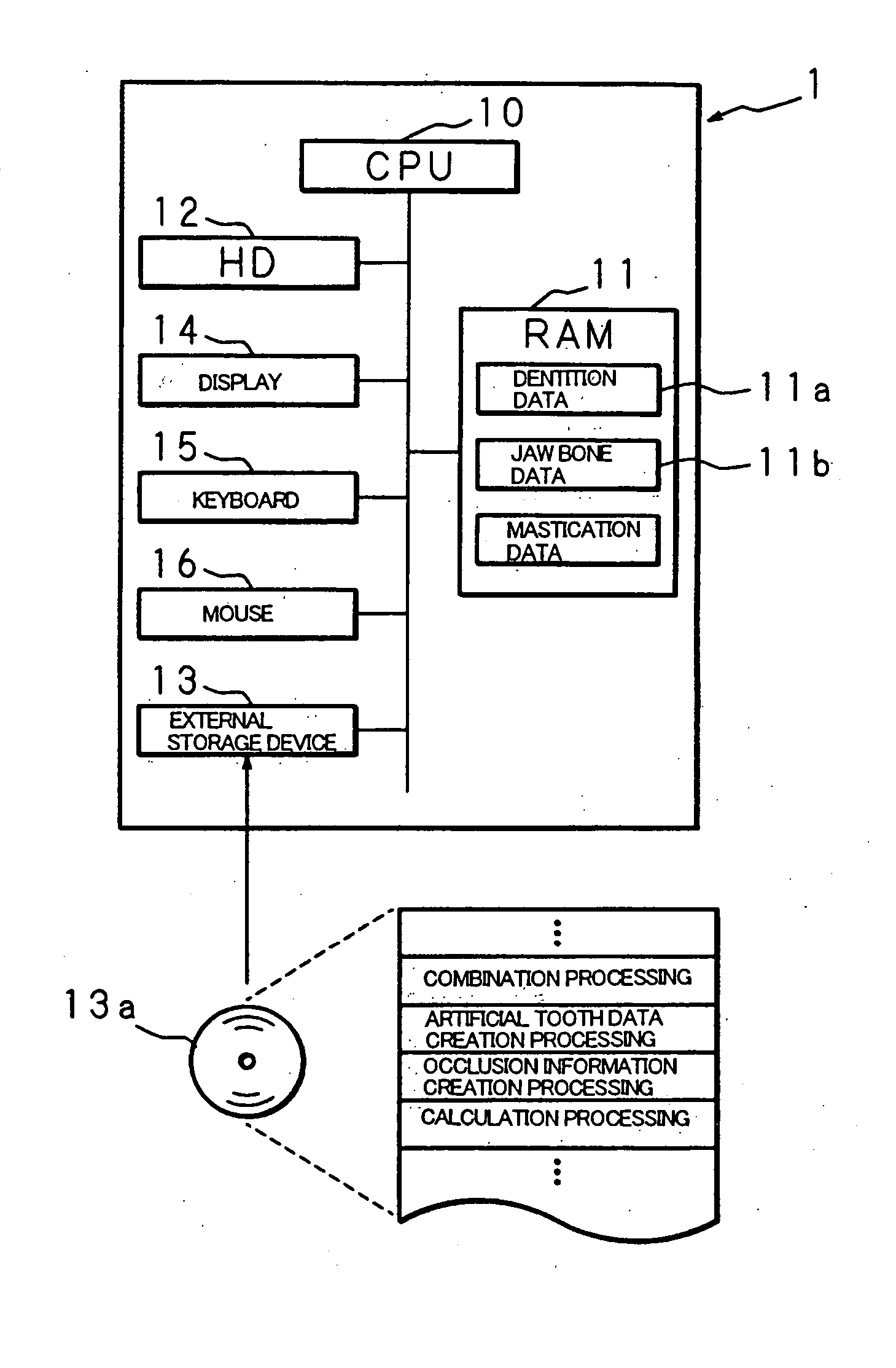
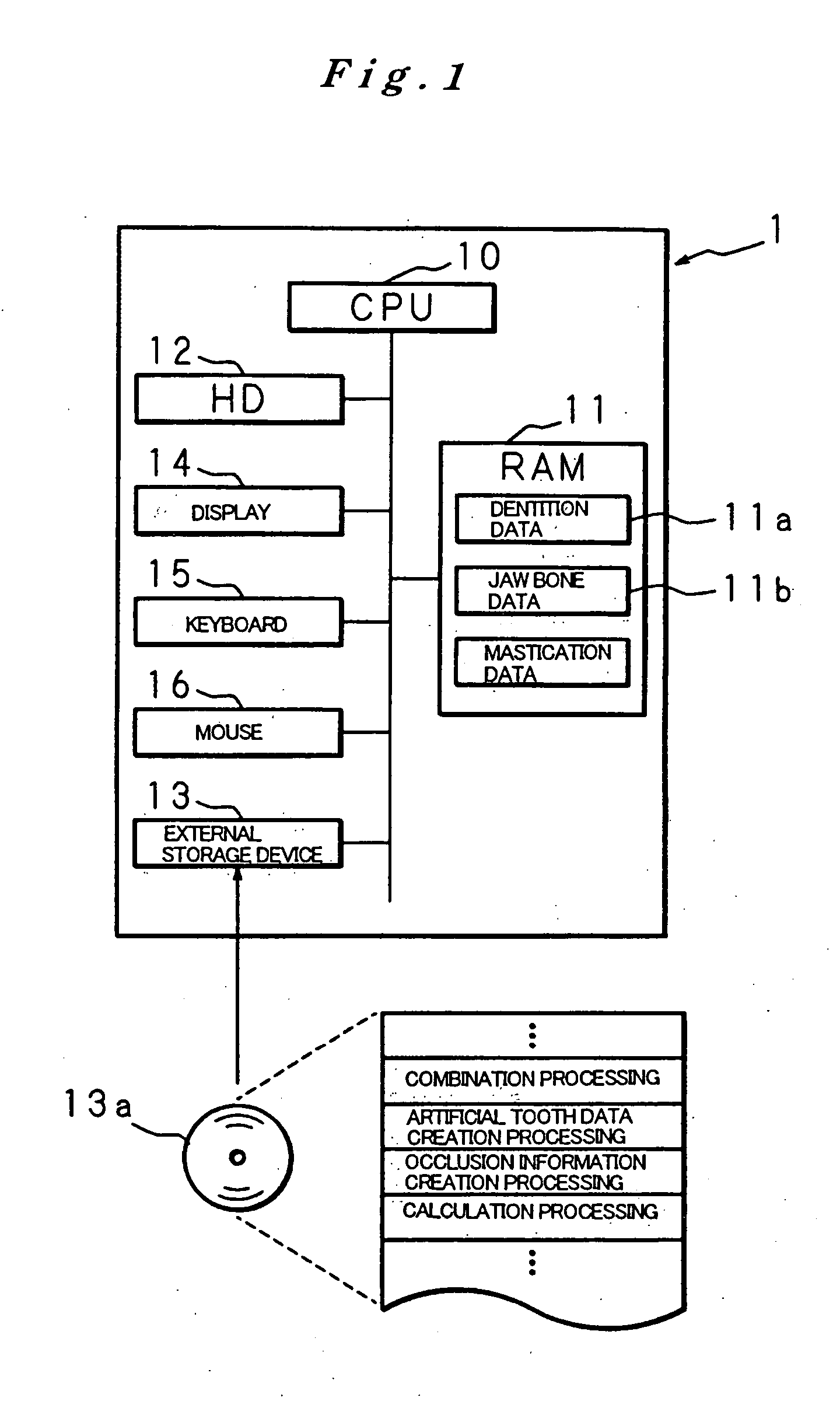
[0073]FIG. 1 is a block diagram showing one example of the construction of an artificial tooth root implantation position determining instrument constituting a first embodiment of the present invention. FIG. 1 shows a computer constituting the artificial tooth root implantation position determining instrument of the present invention.

[0074] The computer 1 comprises a CPU 10, RAM 11, hard disk (hereafter referred to as an “HD”) 12, external storage device 13, display 14, keyboard 15, mouse 16 and the like.

[0075] The CPU 10 is connected to the various abovementioned hardware parts of the computer 1 via a bus; this CPU 10 controls these hardware parts, and successively executes computer programs stored in the HD 12. The HD 12 stores various computer programs that are necessary for the operation of the artificial tooth root implantation position determining instrument of the present invention.

[0076] The RAM 11 is constructed from an SRAM, DRAM, flash memory or the like, and stores te...

second embodiment

[0220]FIG. 17 is a block diagram showing an example of the construction of an artificial tooth root implantation position determining instrument constituting a second embodiment of the present invention. In FIG. 17, constituent members that are the same as in FIG. 1 are labeled with the same symbols, and a description of such constituent members is omitted.

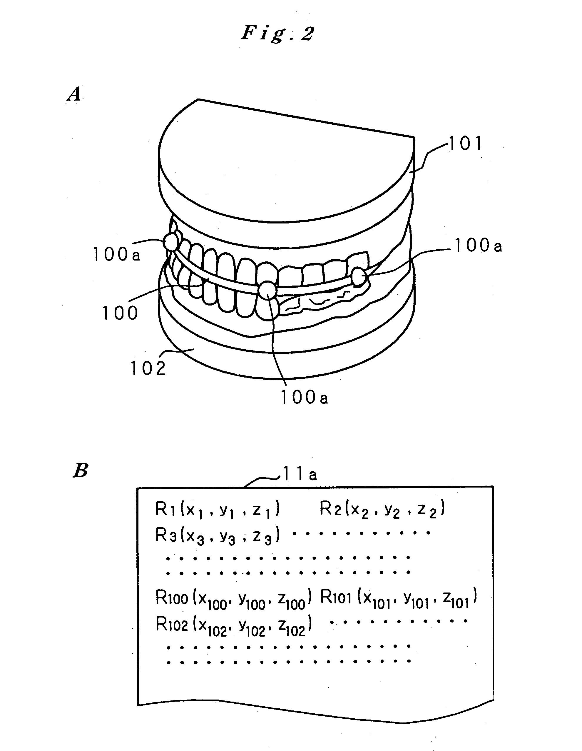
[0221] Like the computer 1 of the abovementioned first embodiment, the computer la of the second embodiment combines dentition data 11a and jaw bone data 11b acquired from the outside, and creates dental crown data indicating a dental crown that will repair the lost portion of the dentition on the basis of this combined data.

[0222] Furthermore, in the computer 1a, the CPU 10 operates as candidate receiving means that receive a plurality of sets of candidate data (two sets of candidate data in the present embodiment) for the artificial tooth root implantation position from the dental physician on the basis of combined data in whi...


PUM

PropertyMeasurementUnit
diameteraaaaaaaaaa
sizeaaaaaaaaaa
mechanical evaluationaaaaaaaaaa

Abstract

Dentition three-dimensional data and jaw-bone three-dimensional data are collected from a patient and they are combined. According to the combined data, dental crown data for making up for data on a lost tooth and occlusion data on a dental crown represented by the dental crown data are created. When an occlusion force according to the occlusion data is exerted on the occlusion face of a dental crown, a mechanical evaluation factor is produced in a jaw bone. The mechanical evaluation factor produced near the place where an artificial tooth root supporting a dental crown is to be implanted is calculated. The implantation place is determined so that the mechanical evaluation factor may be smaller and the mechanical load on the jaw bone from the opposed tooth during mastication may be lighter.

Description

TECHNICAL FIELD [0001] The present invention relates to an artificial tooth root implantation position determining instrument for determining, on the basis of mechanical analysis, the implantation position of an artificial tooth root for supporting false teeth that supplement lost portions of dentition, an artificial tooth root implantation position determining method, a computer program for realizing this instrument, and a recording medium for recording this computer program. Furthermore, the present invention relates to a guide member manufacturing device for manufacturing a guide member that is used in boring an artificial tooth root cavity on the basis of data created by the abovementioned artificial tooth root implantation position determining instrument, a sensor that detects the boring direction of the boring device that bores the artificial tooth root cavity, a drill which has marks indicating the boring depth, and which is mounted in the boring device, and an artificial too...

Claims


Application Information

Patent Timeline
Patent Type & Authority Applications(United States)
IPC IPC(8): A61C8/00A61C19/00A61C1/08A61C13/00A61C19/04
CPCA61C1/084A61C8/00A61C13/0004Y10T29/52A61C8/009A61C13/08A61C19/04A61C19/00A61C8/0089G16H20/40
Inventor SOGO, MOTOFUMIMAEDA, YOSHINOBUTSUTSUMI, SADAMI
Owner CAT CORP
Why Eureka
Try Eureka