Enhanced cross stream mechanical thrombectomy catheter with backloading manifold

a technology of thrombosis catheter and backloading manifold, which is applied in the field of thrombosis catheter, can solve the problems of guidewire not being reliably retracted from the catheter, inability to repair the vessel by multiple inflow/outflow, and internal turbulent eddies consumed the area, and achieves the effect of increasing the flow

Inactive Publication Date: 2006-06-15
MEDRAD INC.
View PDF8 Cites 160 Cited by
  • Summary
  • Abstract
  • Description
  • Claims
  • Application Information

AI Technical Summary

Benefits of technology

[0006] There is yet another benefit to the asymmetrical design of the present invention at the catheter distal end where all of the jet stream outflow is directed from one side of the catheter distal end resulting in a powerful concentration of directed force and increased flow caused by removal or proximal retardation of the guidewire. Such benefit results in the distal portion of the catheter reactingly being directed and forced against the vessel wall opposite to the cross stream action. This movement

Problems solved by technology

In current cross stream catheters, vessel damage by the multiple inflow/outflow cross stream catheters involves the vessel wall being sucked into the catheter at the side inlet orifice of the catheter.
However, in the multiple orifice pair arrangements of the prior art, internal turbulent eddies consumed the area and an increase in performance often did not accompany the retraction of the guidewire.
Furthermore, in existing designs, a guidewire cannot be reliably retracted from the catheter without the potential of the guidewire exiting the inflow ori

Method used


Image

  • Enhanced cross stream mechanical thrombectomy catheter with backloading manifold
  • Enhanced cross stream mechanical thrombectomy catheter with backloading manifold
  • Enhanced cross stream mechanical thrombectomy catheter with backloading manifold

Examples


Embodiment Construction

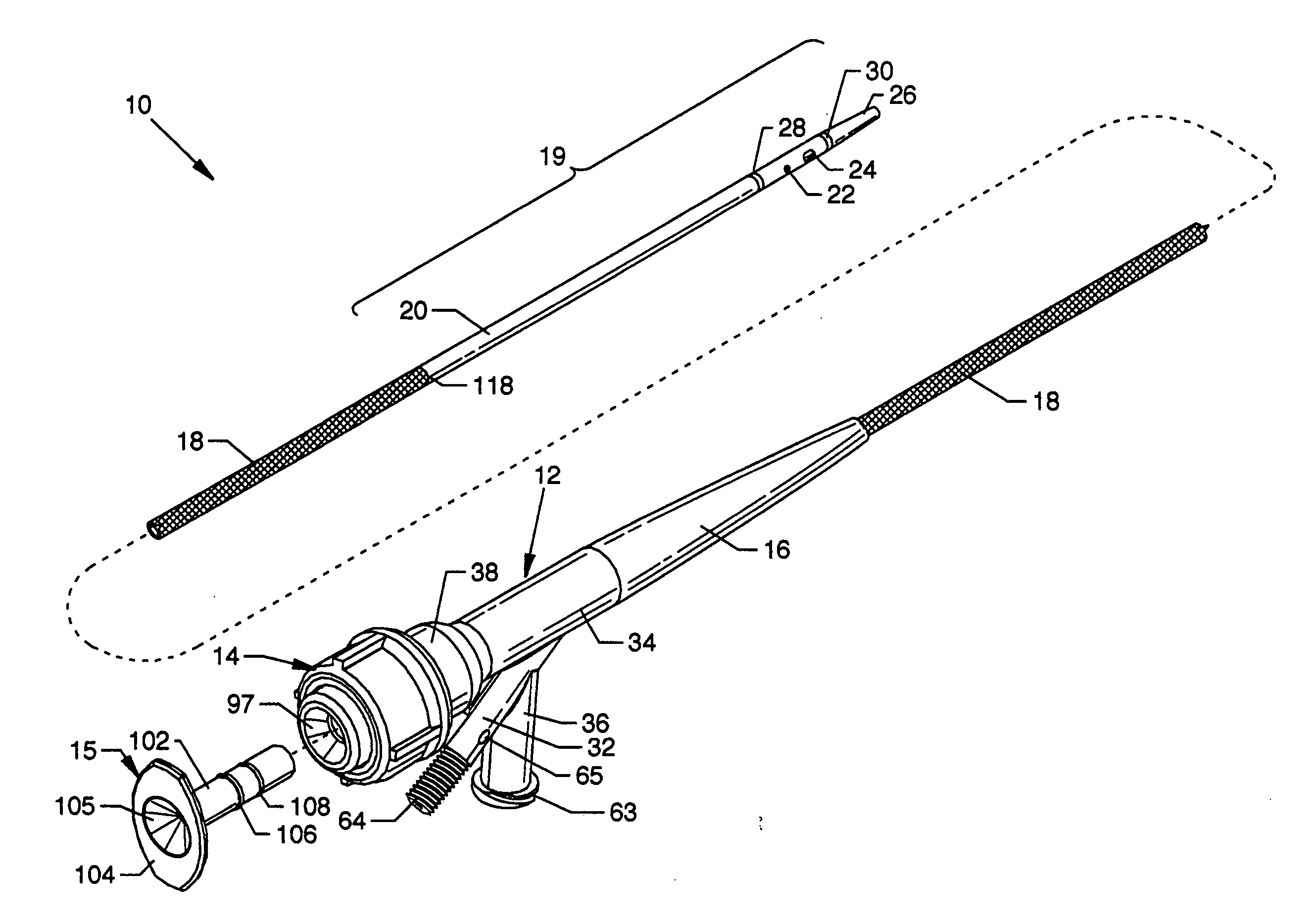
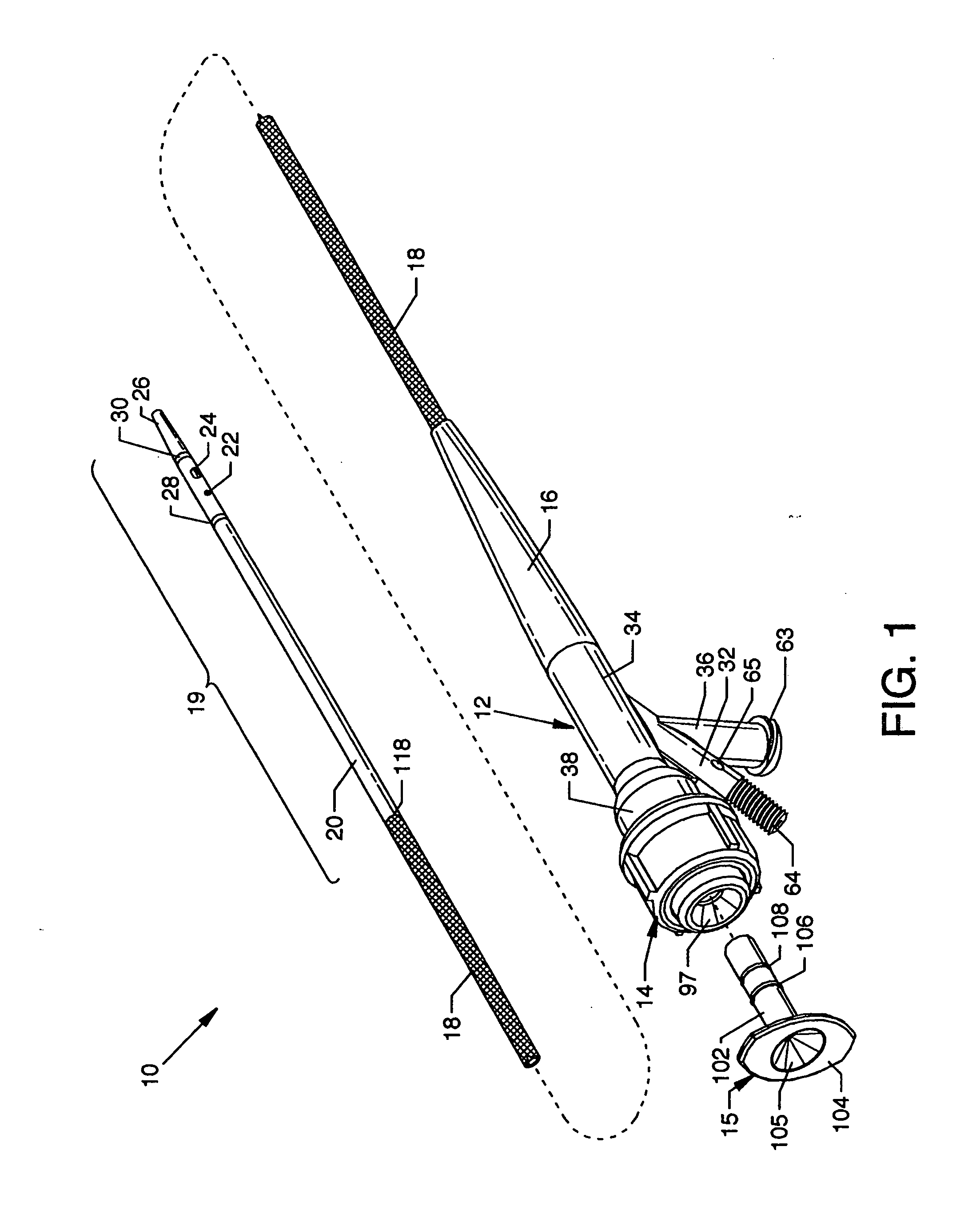
[0062]FIG. 1 is an isometric view of an enhanced cross stream mechanical thrombectomy catheter with backloading manifold 10, the present invention. Externally visible major components of the invention include a centrally located backloading manifold 12, a hemostatic nut 14 threadingly secured to the backloading manifold 12, an introducer 15, a flexible and tapered strain relief 16 connected to and extending from the backloading manifold 12, a catheter tube composed of a braided catheter tube 18 of flexible or semi-flexible material, preferably polyimide or other such suitable composition, connected to the backloading manifold 12 and extending through the tapered and flexible strain relief 16 and a smooth catheter tube assembly 19 having a smooth catheter tube 20 of plastic composition connected to and extending distally from the braided catheter tube 18, and an outflow orifice 22 and an inflow orifice 24 located in longitudinal alignment along an imaginary line at the distal portion...


PUM

PropertyMeasurementUnit
Pressureaaaaaaaaaa
Pressureaaaaaaaaaa
Forceaaaaaaaaaa

Abstract

An enhanced cross stream mechanical thrombectomy catheter with backloading manifold having a distal end with outflow and inflow orifices at one side for producing concentrated cross stream jet flow for selective and concentrated thrombus ablation during thrombectomy procedures. The invention provides for suitable distancing of high powered ablation or suction forces from the near walls of the vasculature. Cross stream flow emanating from the one side of the distal end of the catheter resultantly urges the distal end of the catheter and thus the opposing non-orificed side of the distal end of the catheter toward and against the vascular wall to inhibit contact of the inflow orifice with the vascular wall. Features of the invention include a geometrically configured insert to facilitate the backloading or exchange of guidewires.

Description

CROSS REFERENCES TO RELATED APPLICATIONS[0001] This patent application is related to patent application Ser. No. 10 / 455,096 filed Jun. 05, 2003, entitled “Thrombectomy Catheter Device Having a Self-Sealing Hemostatic Valve,” which is pending. BACKGROUND OF THE INVENTION [0002] 1. Field of the Invention [0003] The present invention is for a thrombectomy catheter, and more particularly, relates to an enhanced cross stream mechanical thrombectomy catheter which accommodates interchanging of guidewires through rear loading of a guidewire, as well as loading of a guidewire in a conventional manner, and also provides for improved cross stream ablation at a thrombus site. The intended use of this invention is for the detachment and removal of unwanted tissues, such as thrombus, from within biological conduits. [0004] 2. Description of the Prior Art and Comparison to the Present Invention [0005] In current cross stream catheters, vessel damage by the multiple inflow / outflow cross stream cat...

Claims


Application Information

Patent Timeline
IPC IPC(8): A61M31/00
CPCA61B17/22A61B17/32037A61B2017/22079A61B2017/22084A61B2217/005Y10T29/49826A61M25/0032A61M25/0045A61M25/005A61M25/007A61M2025/0034A61M25/0029
Inventor BONNETTE, MICHAEL J.THOR, ERIC J.SCHROM, MICHAEL P.
Owner MEDRAD INC.
Why Eureka
Try Eureka