
Manufacturing method of non-reciprocal circuit device

Active Publication Date: 2006-06-22
TDK CORPARATION
View PDF4 Cites 0 Cited by
  • Summary
  • Abstract
  • Description
  • Claims
  • Application Information

AI Technical Summary

Benefits of technology

[0011] It is an object of the present invention to provide a manufacturing method of producing a non-reciprocal circuit device, which has been considerably reduced in size as compared with a conventional counterpart, with excellent mass productivity.
[0015] That is, the support substrate in which many support portions are arranged in a lattice-like form is manufactured to improve efficiency of a manufacturing process of the support portions. Further, the gyromagnetic components and the permanent magnet plate are superimposed on this support substrate, then cutting processing is applied, and each assembly including the support substrate, the gyromagnetic component and the permanent magnet is individually taken out. Therefore, the mass productivity is greatly improved, thereby providing a small and inexpensive non-reciprocal circuit device.
[0019] The mass productivity is likewise improved by this manufacturing method, thereby providing a small and inexpensive non-reciprocal circuit device.
[0020] As described above, according to the present invention, it is possible to provide a manufacturing method of producing a non-reciprocal circuit device, which is smaller than a conventional counterpart, with excellent mass productivity.

Problems solved by technology

However, even if such a configuration as disclosed in Patent References 1 and 2 is adopted, the case has been conventionally considered to be an essential constituent part in order to assuredly couple central constituent parts such as a gyromagnetic component or a magnet with each other, and hence there is a limit in a reduction in size.
Further, after the gyromagnetic component, the permanent magnet or the like and the case are produced in different processes, the gyromagnetic component, the permanent magnet and electric components such as a matching capacitor or a terminating resistor must be incorporated in the case to manufacture a non-reciprocal circuit device, there is also a limit in an improvement of mass productivity.

Method used


Image

  • Manufacturing method of non-reciprocal circuit device
  • Manufacturing method of non-reciprocal circuit device
  • Manufacturing method of non-reciprocal circuit device

Examples


Embodiment Construction

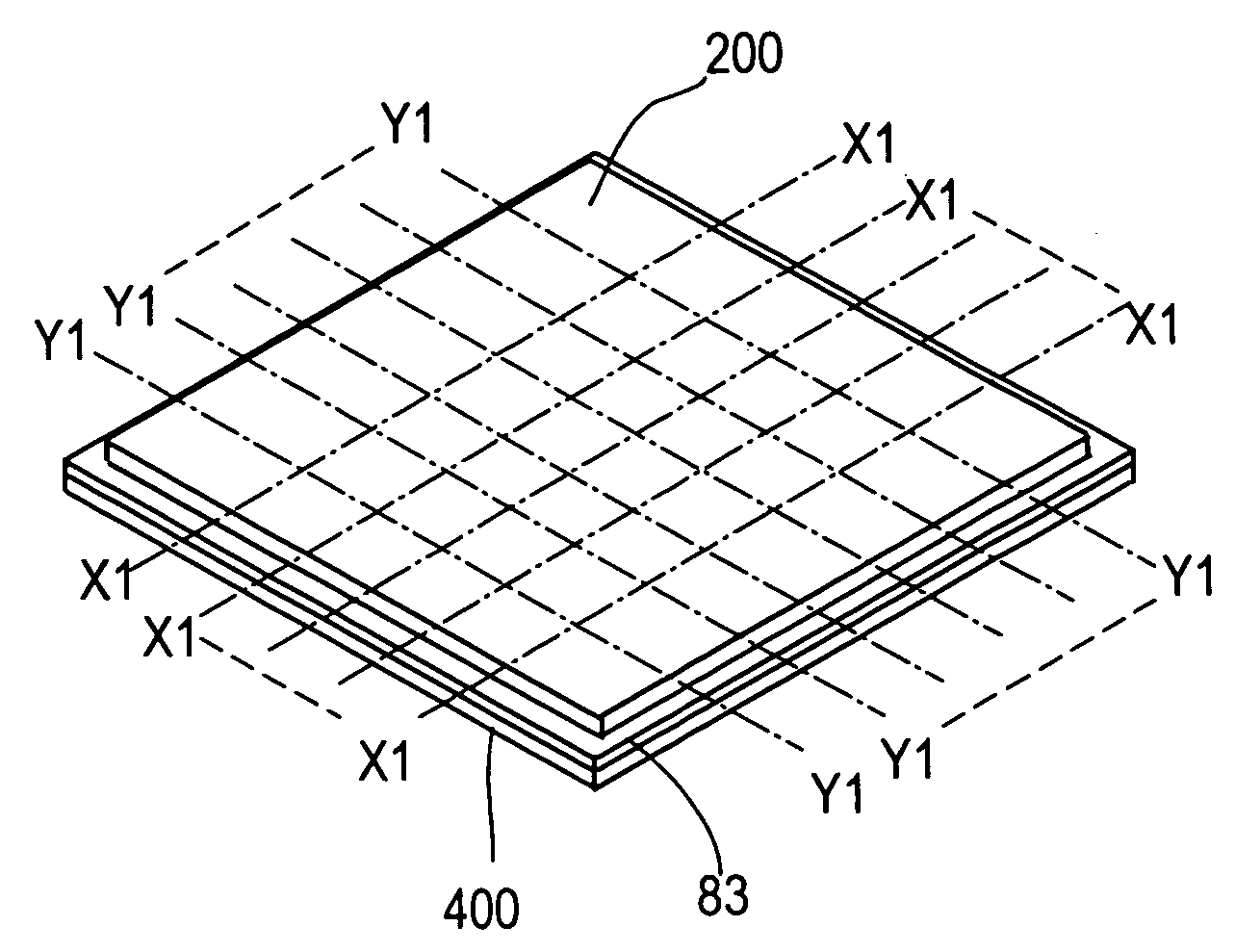
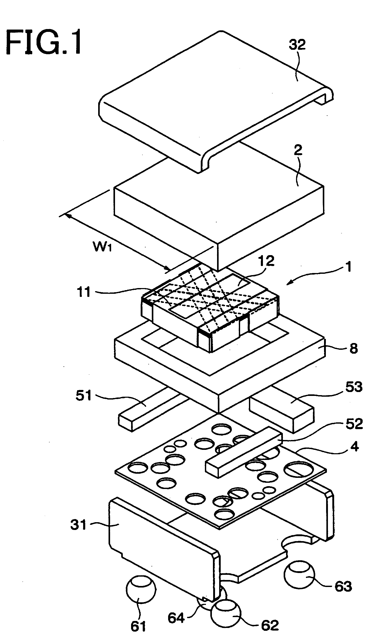
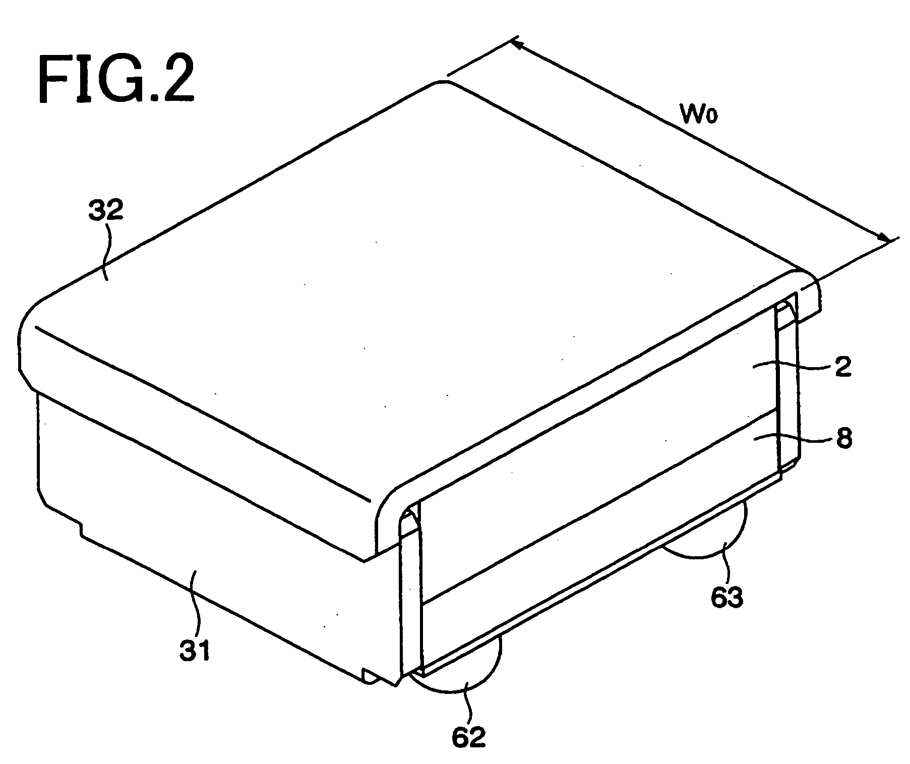
[0037] Prior to explaining a manufacturing method according to the present invention, a non-reciprocal circuit device manufactured by this manufacturing method will be described. FIGS. 1 to 3 show an example of an isolator.

[0038] The illustrated non-reciprocal circuit device has a gyromagnetic component 1, a permanent magnet 2, a first yoke 31 and a second yoke 32 as its essential constituent parts. In the embodiment, it further has a support substrate 4, capacitors 51 and 52, a terminating resistor 53 and a plurality of metal balls 61 to 64 which serve as input / output terminals and ground terminals.

[0039] As shown in FIG. 3, the gyromagnetic component 1 includes a center electrode 11 and a soft magnetic substrate 12. The center electrode 11 includes first to third central conductors 111 to 113. The first to third central conductors 111 to 113 branch from three sides of a substantially square ground portion which is in contact with a lower surface of the soft magnetic substrate 12...


PUM


Abstract

There is provided a manufacturing method of producing a non-reciprocal circuit device, which is much smaller than a conventional counterpart, with excellent mass productivity. A support substrate 400 having support portions Q11 to Qnm arranged therein in a lattice-like form is produced, and a previously manufactured gyromagnetic component 1 is bonded on each of the support portion Q11 to Qnm. Then, a permanent magnet plate 200 is bonded. The permanent magnet plate 200 has a plane area which covers all the gyromagnetic components 1. Subsequently, the entire structure is cut along lines X1-X1 and lines Y1-Y1 in accordance with each gyromagnetic component 1.

Description

BACKGROUND OF THE INVENTION [0001] 1. Field of the Invention [0002] The present invention relates to a method of manufacturing a non-reciprocal circuit device such as an isolator or a circulator. [0003] 2. Description of the Related Art [0004] A non-reciprocal circuit device such as an isolator or a circular is used in, e.g., a mobile wireless device such as a mobile phone. This type of non-reciprocal circuit device is configured to accommodate a gyromagnetic component constituted of a soft magnetic substrate, a center electrode and others, a permanent magnet, a matching capacitor(s) and a terminating resistance in a case functioning as a yoke and an insulator as typified by, e.g., Patent References 1 and 2. [0005] The gyromagnetic component, the permanent magnet or the like and the case are independent components. Therefore, it is a conventional general technique to manufacture these components in different processes and then incorporate the gyromagnetic component, the permanent ma...

Claims


Application Information

Patent Timeline
IPC IPC(8): H01F7/06
CPCH01P11/00Y10T29/435Y10T29/49075Y10T29/4902Y10T29/49798
Inventor KINOSHITA, TSUYOSHIIDETA, SHUNSUKE
Owner TDK CORPARATION
Features
  • Generate Ideas
  • Intellectual Property
  • Life Sciences
  • Materials
  • Tech Scout
  • Unparalleled Data Quality
  • Higher Quality Content
  • 60% Fewer Hallucinations
Learn More