
Virtual controller for mixed air low temperature protection of HVAC systems

a low temperature protection and virtual controller technology, applied in ventilation systems, heating types, domestic cooling devices, etc., can solve the problems of difficult installation of physical inability to install low temperature protection sensors and control, and condensation or freezing in hvac cooling and/or heating coils, etc., to achieve the effect of increasing the temperature of the mixed air stream

Inactive Publication Date: 2006-06-22
HONEYWELL INT INC
View PDF4 Cites 57 Cited by
  • Summary
  • Abstract
  • Description
  • Claims
  • Application Information

AI Technical Summary

Benefits of technology

[0007] In one example, the air in the first flow input may be fresh outdoor air, the air in the second flow input may be return air, and the air in the flow output may be a supply air. The AHU may measure or otherwise determine the temperature and air flow of the fresh outdoor air, the temperature of the return air, and the air flow of the supply air. From this, the AHU may calculate the air temperature of the mixed air stream that passes to the HVAC cooling c...

Problems solved by technology

If the mixed air temperature is too low, it may cause condensation or freezing in the HVAC cooling and / or heating coils, which in many cases, is undesirable.
In the case of modular or packaged air handling unit components, it is difficult to install low temperature protection sensors and control.
In some cases it may be physically impossible to install an averaging or other sensor in the mixed air stream plenum of many HVAC economizers.
In other cases, the economizer outdoor air dampers, airflow station, and controller are fabricated and shipped as an enclosed module, which makes it difficult or impossible to install a mixed air low temperature sensor / controller.

Method used


Image

  • Virtual controller for mixed air low temperature protection of HVAC systems
  • Virtual controller for mixed air low temperature protection of HVAC systems
  • Virtual controller for mixed air low temperature protection of HVAC systems

Examples


Embodiment Construction

[0016] The following description should be read with reference to the drawings wherein like reference numerals indicate like elements throughout the several views. The detailed description and drawings show several embodiments which are meant to be illustrative of the claimed invention.

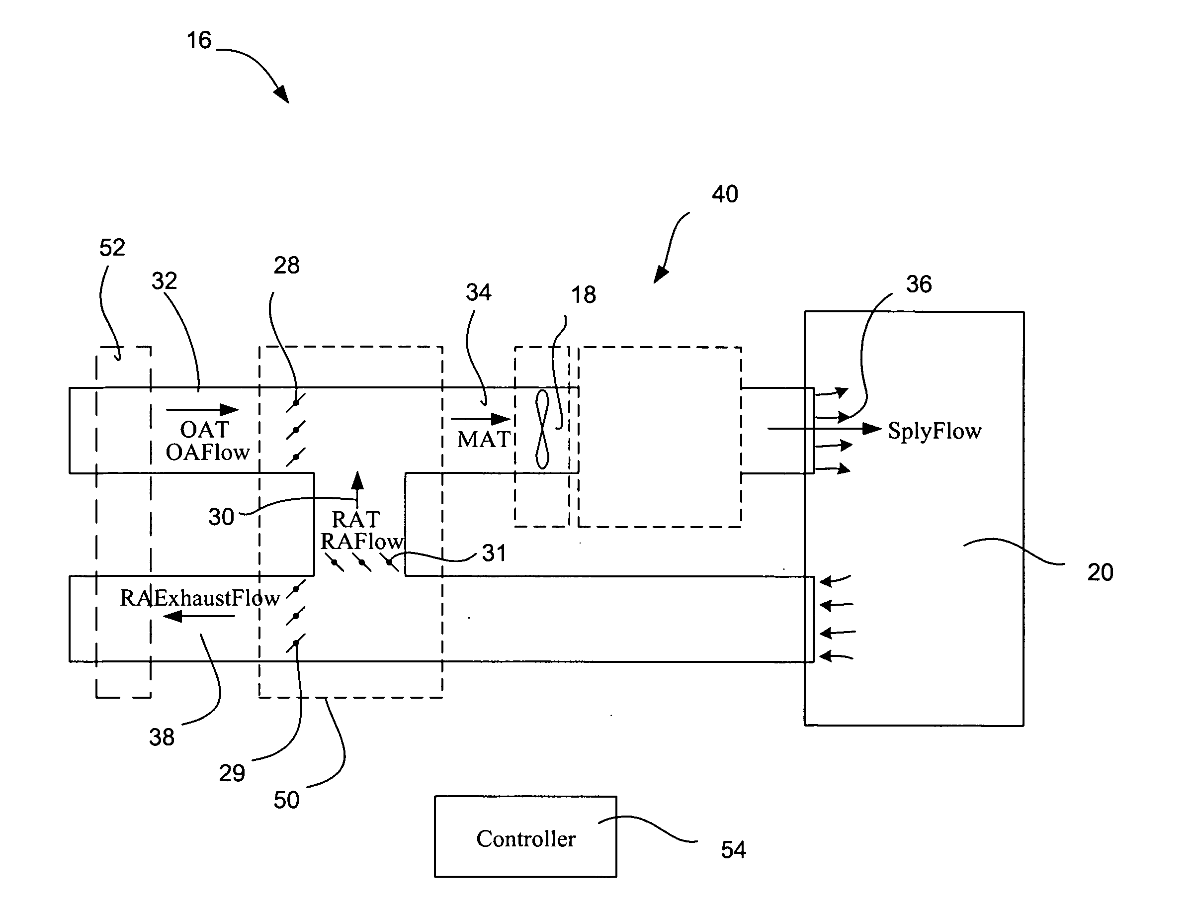
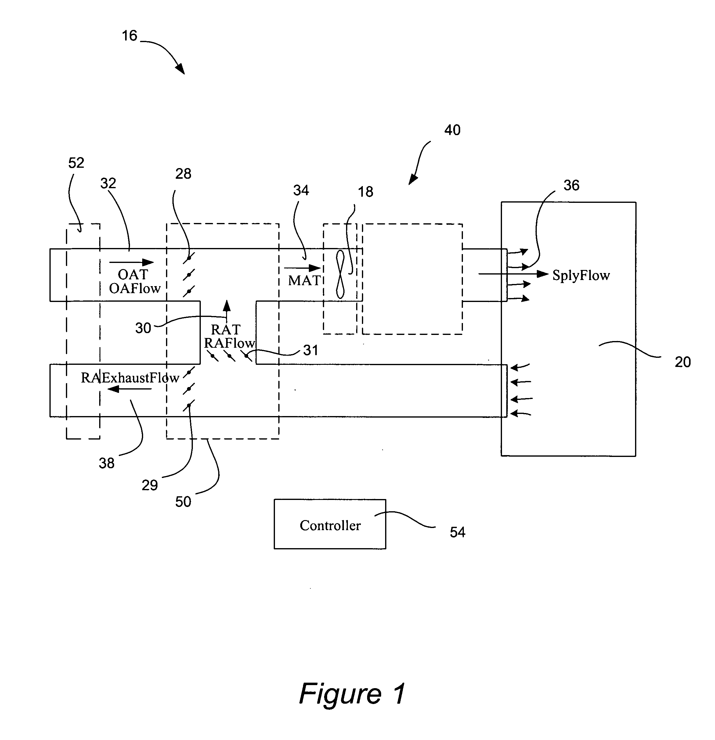
[0017]FIG. 1 is a schematic diagram of an illustrative air handling unit (AHU) 16 in a building 20. The building 20 may be a residential, commercial, or any other suitable building, as desired. The AHU 16 may include a heating, ventilation, and air conditioning (HVAC) unit 40, which in some cases, may include one or more cooling and / or heating coils. In the illustrative embodiment, the AHU 16 includes at least two inputs and one output. A first input may correspond to the fresh outdoor air input 32. The temperature and / or flow rate of the fresh outdoor air input may be measured or otherwise determined by one or more sensors, by computational methods, and / or any other method as desired. Additionally, ...


PUM


Abstract

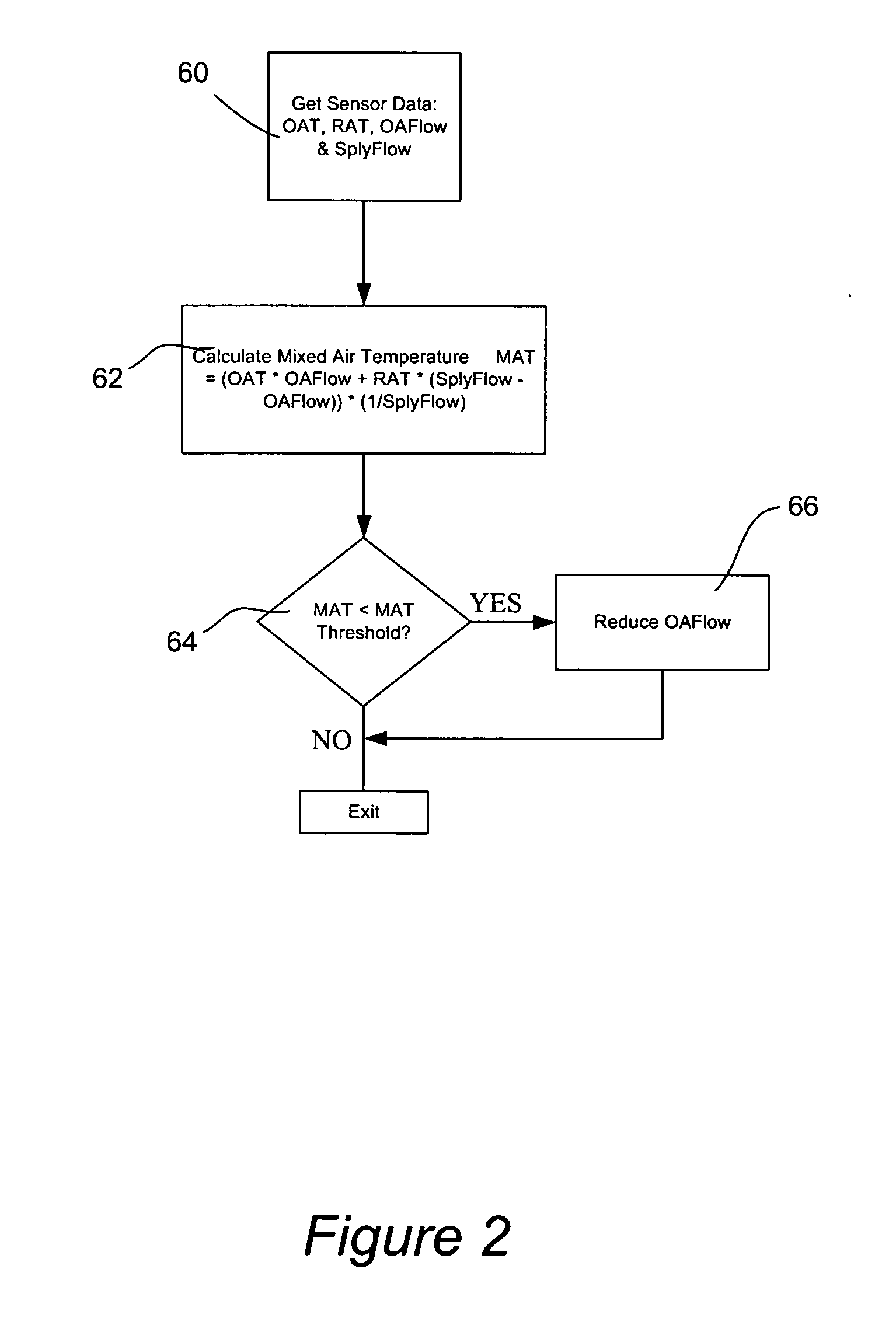
A method for protecting an HVAC system of an air handling unit from low temperature outdoor ventilation air. The air handling unit may include an outdoor fresh air region, a return air region, a supply air region, and a damper situated in or adjacent to the fresh air region to regulate the flow of outdoor air into the air handling unit. The air handling unit mixes the outdoor fresh air and the return air to provide a mixed air stream to the HVAC system. In one illustrative embodiment, one or more sensors are used to measure the temperature and flow rate of the air entering or passing through the outdoor fresh air region, the temperature of the air entering or passing through the return air region and the flow rate of the air passing through the supply air region. The temperature of the mixed air stream, which is provided to the HVAC system, is then calculated using a controller or the like. In some cases, when the temperature of the mixed air stream falls below a threshold value, the controller may instruct the damper to close and reduce the fresh outdoor air that is brought into the air handler unit. Various other embodiments and algorithms are disclosed.

Description

FIELD [0001] The present invention relates generally to Heating, Ventilation, and Air Conditioning (HVAC) systems, and more particularly to methods and apparatus for regulating the flow of outdoor air to help protect the HVAC systems from low temperature air. BACKGROUND [0002] Modern buildings have an HVAC system that is used to control the environment of the building's inside space. In many systems, air from the building's inside space is drawn into return ducts and provided back to the HVAC system. To meet desired ventilation requirements, many HVAC systems include an exhaust port for exhausting at least some of the return air to the outside environment, and an intake port for bringing in fresh air to the HVAC system. In some cases, a damper is provided that selects how much return air is exhausted and how much outside air is brought into the building. Thus, and depending on the conditions, the air entering the rooms is often a mixture of fresh outdoor air and return air. [0003] I...

Claims


Application Information

Patent Timeline
IPC IPC(8): F25B49/00F25D17/00F25D17/04
CPCF24F7/08F24F11/001F24F11/0012Y02B30/78F24F13/08F24F2011/0006F24F2011/0026F24F11/0015F24F11/30F24F2110/00F24F2110/10F24F2110/20F24F2110/70Y02B30/70F24F11/76F24F11/62
Inventor WRUCK, RICHARD A.WEBER, LARRY E.
Owner HONEYWELL INT INC
Learn More